Leading up to today’s discussion, we previously reviewed the differences between stateful and stateless firewalls , followed by how stateful NAT services operate in conjunction with a stateful Gateway Firewall. While the expectation when using stateful NAT services in NSX is that the Gateway Firewall is enabled with a stateful policy, we wanted to show the potential impact of using a stateful NAT service when the Gateway Firewall is disabled or operating in a stateless manner.
Why so much focus on the firewall state table?
Some users of NSX using only stateful NAT services on a T0/T1 SR come to the conclusion that the Gateway Firewall itself is not providing any real value with its default ‘Allow Any‘ rule. With this idea in mind, an individual can remove stateful firewall functionality via the following options:
- Disabling the Gateway Firewall function entirely
- Creating a new firewall policy above the built-in default policy with ‘Stateful‘ set to ‘off‘, and then creating a new ‘Allow Any‘ rule within this policy.
Note: By definition, processing stateless firewall rules will utilize more CPU than disabling the Gateway Firewall entirely, but for purposes of our evaluation today, both of these options functionally accomplish the same thing: removing the creation of state table entries by firewall rules.
Even with the Gateway firewall itself disabled or using stateless firewall rules, NSX stateful NAT services like SNAT and DNAT still create state table entries on their own. Without firewall rules also supplying state entries, you may discover some unintended consequences when utilizing stateful NAT services.
With this in mind, we’ll review 2 different scenarios with the Gateway Firewall disabled:
- Traffic initiated S-to-N of a T1 SR with SNAT – this would be when a VM has initiated traffic that is egressing a T1 SR and is intended to be SNAT’d
- Traffic initiated N-to-S of a T1 SR with SNAT – this is when a VM has initiated traffic that is ingressing a T1 SR and should not be SNAT’d
Let’s take a look below at each of these scenarios in more depth.
Traffic initiated S-to-N of T1 SR with SNAT
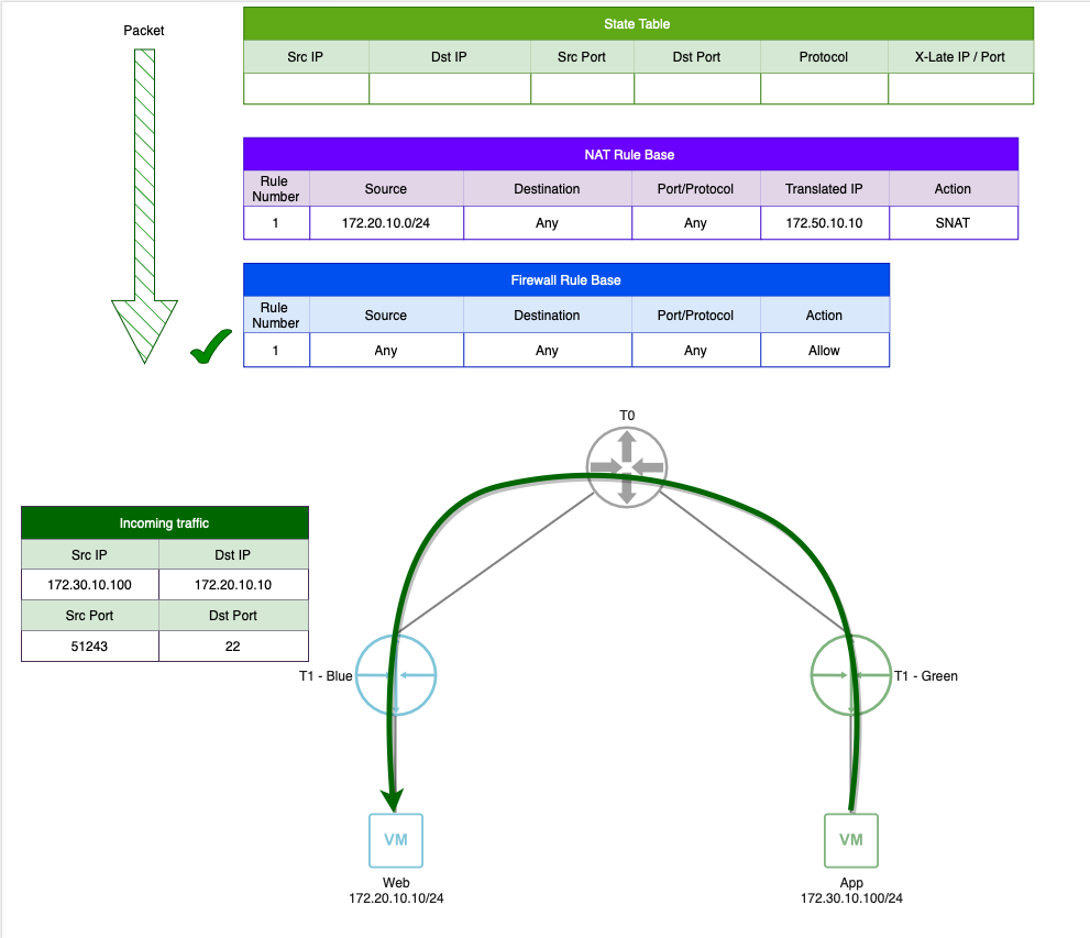
Below we can see traffic is initiated from the ‘Web‘ VM matching the SNAT entry in the NAT Rule Base. Since we’ve disabled the Gateway firewall, there is no Firewall Rule Base; if traffic matches a NAT rule, the appropriate NAT action will be taken, and if it does not match a NAT rule, it will simply be routed unimpeded.
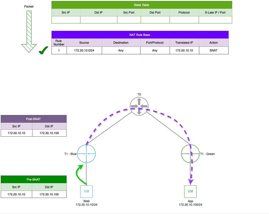
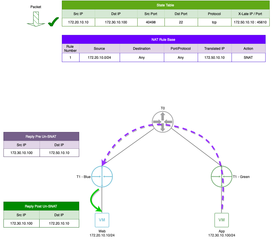
In the above, by matching the SNAT rule, the SNAT action is taken on the packet and it is routed on to the ‘App‘ VM. As SNAT is a stateful service, new matching traffic results in the creation of an entry in the State table, which is shown below.

Finally, for all remaining traffic in this session, traffic matches the State table entry and results in the appropriate action, either SNAT’ing the traffic as it egresses ‘T1 – Blue‘ headed north to the ‘App‘ VM, or un-SNAT’ing the traffic as it ingresses ‘T1 – Blue‘ heading south to the ‘Web‘ VM. Depicted below, we can see reply traffic matching the State table entry and being un-SNAT’d before being delivered to the ‘Web‘ VM.
In short, S-to-N traffic utilizing a SNAT rule with the Gateway Firewall disabled should work exactly as one would expect.
Traffic initiated N-to-S of T1 SR with SNAT
Now let’s look at a scenario where we want to allow the ‘App‘ VM to SSH to the ‘Web‘ VM using the actual IP addresses of the VMs. Since we’ve disabled the Gateway Firewall, and the traffic itself does not match the criteria of the existing SNAT rule, the ‘App‘ VM can successfully send traffic to the ‘Web‘ VM unaltered, as shown below.
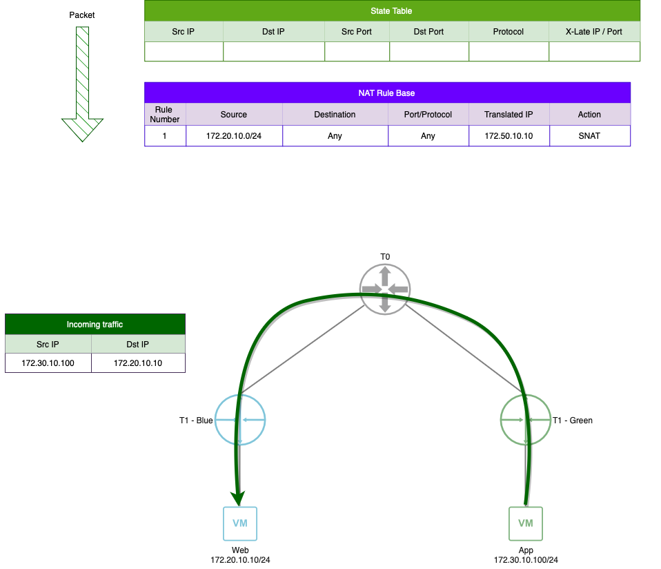
As the initial packet didn’t match our SNAT rule, no state table entry is created. However, without a state table entry, reply traffic from the ‘Web‘ VM will be evaluated against the rules of the NAT Rule Base on the ‘T1 -Blue‘ SR. As the SNAT rule is designed to match against any traffic with a source in the ‘172.20.10.0/24‘ subnet, this results in a match, and the reply traffic is SNAT’d as it egresses ‘T1 – Blue‘ destined for the ‘App‘ VM.
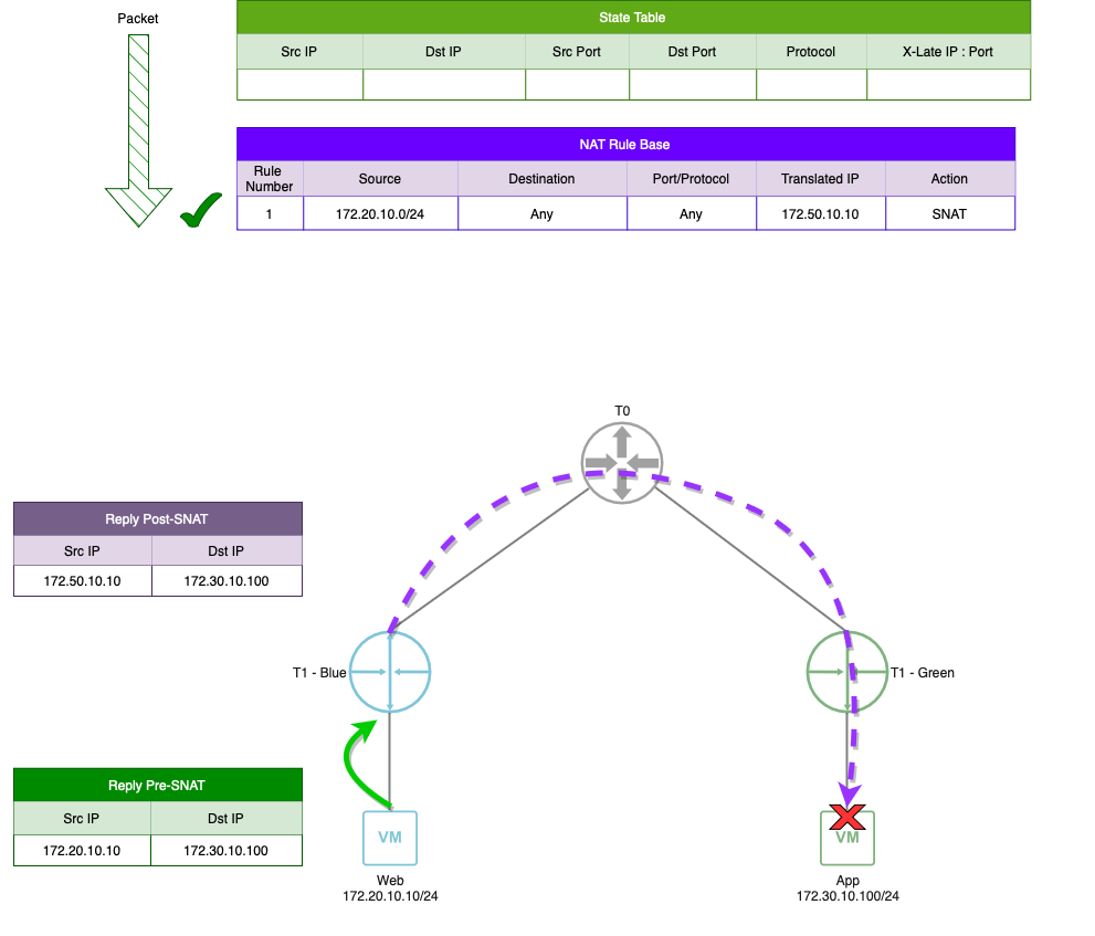
Obviously, this breaks our communication, as the ‘App‘ VM is expecting a reply from ‘172.20.10.10‘ but receives one from ‘172.50.10.10‘ (the SNAT address).
How would utilizing the stateful firewall remediate the above issue?
While we are going to discuss our available options with the Gateway Firewall disabled, let’s briefly review how a stateful firewall remediates the N-to-S issue described in the previous section.
Just like before, the initial communication from ‘App‘ to ‘Web‘ doesn’t match the NAT rule itself, so it’s bypassed. However, with a stateful Firewall enabled, the traffic matches the ‘Allow Any‘ rule in the firewall rule base. This successful match results in the creation of state table entry (not depicted above, but the resulting state table entry is in the below image).

When ‘Web‘ replies to ‘App‘, the reply traffic matches against the corresponding state table entry, bypassing the NAT and Firewall rules entirely. The packet remains unaltered, and is successfully delivered to ‘App‘. As such, communications between ‘App‘ and ‘Web‘ work without issue.
How can the depicted N-to-S issue be remediated without a stateful firewall?
Aside from enabling the Gateway Firewall and using stateful firewall rules, we do have a few options available to us to remediate this scenario. These are:
- Configure a more explicit SNAT rule
- Utilize No-SNAT rules
Configuring a more explicit SNAT rule
Below is an example of reply traffic in the above N-to-S scenario, but with the SNAT rule configured with a specific destination subnet of ‘172.16.10.0/24‘. By configuring a specific destination, we greatly reduce the odds of reply traffic inadvertently matching the SNAT rule. While not depicted in the initial diagram, let’s presume that the ‘App‘ VM is using a randomly selected high source port of ‘51243‘. Just like before, the initial packet from ‘App‘ to ‘Web‘ is delivered without issue (not depicted below).
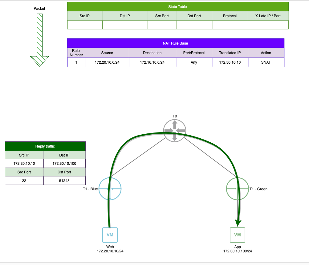
As the reply traffic from ‘Web‘ to ‘App‘ no longer matches the destination IP address criteria in our more explicit SNAT rule, the reply traffic is not SNAT’d, and is delivered to the ‘App‘ VM unaltered. In this example, communication between ‘Web‘ and ‘App‘ will work as desired.
Utilizing No-SNAT rules
However, particularly in the case of SNAT, the intent is typically that all traffic leaving a given boundary (T0 or T1) has SNAT applied regardless of destination. In this case, a ‘No-SNAT‘ rule can prevent reply traffic from unexpectedly being SNAT’d.
Referencing the N-to-S scenario again, the initial traffic from ‘App‘ to ‘Web‘ didn’t match our NAT rule, and it’s successfully received by ‘Web‘ unaltered. To ensure our reply traffic is unaffected, we’ll create a No-SNAT rule in the NAT rule base. It’s key to note that, like any firewall rule base, NAT rules are processed top down. With this in mind, our No-SNAT rule must sit above our SNAT rule in order to ensure it’s enforced first.

In the above image, we depict our No-SNAT rule, with a source of ‘172.20.10.0/24‘ (the ‘Web‘ VM network) and a destination of ‘172.30.10.0/24‘ (the ‘App‘ VM network). The reply traffic from ‘Web‘ to ‘App‘ matches the No-SNAT rule, and, as the name suggests, no SNAT action is performed; the reply traffic is routed on to the ‘App‘ VM unaltered. This flow of communication works successfully.
Note: While the No-SNAT rule above resolves our particular issue with reply traffic accidentally being SNAT’d, it will also prevent any traffic initiated from the ‘172.20.10.0/24‘ network destined to the ‘172.30.10.0/24‘ network from being SNAT’d. This is important to understand in order to avoid potentially causing a different issue by resolving this particular one.
Similar to what we did in the section on configuring a more explicit SNAT rule, we have the option of being more specific with the source and destination IP addresses of the No-SNAT rule. By using the exact IP addresses of the ‘Web‘ and ‘App‘ VMs as the No-SNAT source and destination, respectively) one could narrow what would match the No-SNAT rule. This could potentially be a viable workaround to prevent reply traffic from being SNAT’d while still allowing most of what egresses the T1 to have a SNAT rule applied.
Can the above N-to-S scenario happen with DNAT?
A DNAT rule is NSX is designed to NAT the destination of traffic as it ingresses a T0/T1 SR; it’s functionally the logical opposite of a SNAT rule. A fundamental difference in building SNAT and DNAT rules in NSX is that DNAT requires the configuration of a destination IP address in its ‘Match‘ Criteria. In short, you’re required to enter both the IP address that the outside world will use to access a VM (this would be the DNAT address hosted by the T0/T1) as well as the IP address of the actual destination (the ‘Translated‘ address).
As a DNAT rule requires such specificity, the phenomenon we’ve described above with SNAT rules and reply traffic is unlikely to occur. That is, reply traffic that ingresses a T0/T1 N-to-S can’t inadvertently match a DNAT rule, as this would require the original initiating traffic to be have a source address of the DNAT IP; barring some type of unusual configuration, this shouldn’t be possible.
Next time…
Well, this post ultimately sums up our exploration into how stateful firewalls and stateful NAT rules interact in NSX. In the near future, we’ll be further exploring NAT and its configurations. Hope to see you then!
