In our previous post, we detailed the differences between stateful and stateless firewalls. In today’s post, we’ll investigate how stateful NSX NAT services function in conjunction with the stateful firewall running on a Tier-0 or Tier-1, which is known as the ‘Gateway Firewall‘.
Note: As mentioned in prior posts, we won’t be covering the newer stateful Active/Active (A/A) Tier-0/Tier-1 Service Router (SR) functionality for hosting stateful NAT services. However, the configurations and implications discussed below should be no different for a stateful A/A SR versus stateful Active/Standby (A/S) SR. Remember, SNAT and DNAT cannot operate on a stateless A/A T0 SR.
Default Gateway Firewall for new A/S T0 or T1
When using stateful NAT services in NSX (SNAT and/or DNAT), there’s an expectation that the Gateway Firewall is enabled on the SR that will be performing NAT. As you can see in the below image, When creating an A/S T0 or T1 SR, the Gateway Firewall service is enabled by default.

The Gateway Firewall on the SR possesses a default configuration of a single policy named ‘Policy_Default_infra-tier1-Tier1‘ (this name is dynamically generated based on the name of your T0/T1; in our lab, ‘T1 -Blue‘ is named ‘Tier1‘ ) which is comprised of a single rule named ‘default_rule‘. This rule is configured as an ‘Allow All‘ rule: the source, destination, and service in the rule are all configured for ‘Any‘. You can see an example of this below:

Each policy in the Gateway firewall has a few configurable settings that affect how all of the rules within the policy behave; you can access these settings by clicking the gear symbol on the far right of the policy itself. Reviewing the default settings of the ‘Policy_Default_infra-tier1-Tier1′ policy below, we can see the ‘Stateful‘ setting is configured to ‘Yes‘; this means that our ‘default_rule‘ will create a state entry for any new traffic that matches.
With ‘TCP Strict‘ set to ‘No‘, any TCP packet that enters the firewall, even one part of an existing session, will be allowed and will result in a state entry. If ‘TCP Strict‘ was set to ‘Yes‘, it would mean that all new TCP sessions must first contain only the TCP SYN flag in order to match against any firewall rules.
Note: ‘Locked‘ is an option that may be leveraged to prevent multiple users from editing rules in a policy at the same time. This configuration option has no bearing on our discussions today.

The key takeaway is to understand when creating a A/S T0 or T1 SR, the Gateway Firewall is enabled by default. Additionally, all traffic traversing this SR will match the ‘default_rule‘, and will be allowed. We will see later in this post, new sessions matching this rule result in an entry in the Gateway Firewall’s state table.
Note: For today’s discussion, the T1 SR we have created to perform SNAT is operating with the default firewall configuration described in this section.
Lab Configuration
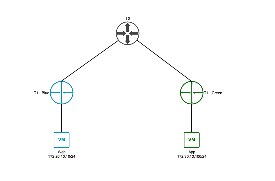
In the diagram below, the ‘Web‘ VM (IP address ‘172.20.10.10/24‘) resides on a network attached to a T1 named ‘T1 – Blue‘, which is configured as an A/S T1. On the right of the diagram, the ‘App‘ VM (IP address ‘172.30.10.100/24‘) resides on a network attached to a T1 named ‘T1 – Green‘, which is configured as a distributed-only T1. This means ‘T1 – Blue‘ can provide stateful services such as SNAT, while ‘T1 – Green‘ cannot.
Lastly, each T1 is uplinked to our T0, which makes it possible for the ‘Web‘ VM and ‘App‘ VM to route to each other.
SNAT Rule configuration

Above is a SNAT rule configured in NSX. Circled in red, you may see the above NAT rule is named ‘snat_172.20.10.0_24‘ and ‘SNAT‘ has been chosen from the ‘Action‘ drop down. Under the ‘Match‘ heading, circled in green, we’ve entered a network of ‘172.20.10.0/24‘ in the ‘Source IP‘ field, which encompasses the entire subnet where the ‘Web‘ VM resides.
We’ve made no entry at all in the ‘Destination IP‘ and ‘Destination Port‘ fields, which means these will functionally behave has an ‘Any‘ for the purposes of matching traffic. Lastly, circled in purple, ‘172.50.10.10‘ has been entered in the ‘Translated IP | Port‘ section for the ‘IP Address‘.
Note: We have left the ‘Select Service‘ drop down under ‘Translated IP | Port‘ untouched, as it provides no value for a SNAT rule.
What this rule created, all traffic initiated from the ‘172.20.10.0/24‘ network egressing ‘T1 – Blue‘ northbound will be SNAT’d to ‘172.50.10.10‘.
SNAT packet flow
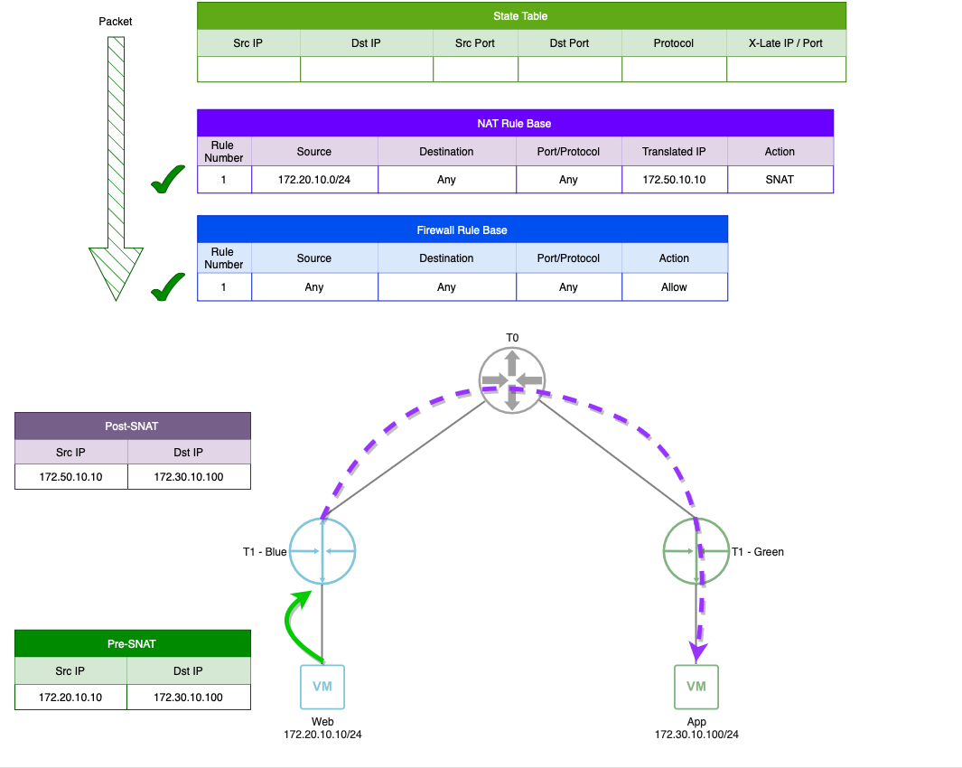
Here we see the traffic being initiated from the ‘Web‘ VM to the ‘App‘ VM with the previously created SNAT rule in place. The curved green arrow at the bottom of the diagram shows our packet from the ‘Web‘ VM being received by the ‘T1 – Blue‘ SR.
Moving our focus to the tables at the top of the diagram, we see a representation of this packet entering the ‘T1 – Blue‘ SR (the green striped straight arrow) and being evaluated against our NAT and firewall rules. As covered in our previous post regarding stateful firewalls, our packet is first compared to the state table, where no entries exist, so it moves onto the NAT rule base, where it matches against our SNAT rule. After evaluating against the NAT rules, this packet is now compared against the firewall rule base, where it matches agains the ‘default_rule’, and is allowed.
Note: If there are no matches for any existing NAT rules, the packet still moves on to the firewall rules for evaluation.
At this point, the packet is successfully SNAT’d, changing the source IP address of the packet to ‘172.50.10.10‘, and is forwarded on to the T0 for routing (depicted by the dashed purple line). As this is a SNAT rule, the destination IP address is unchanged.
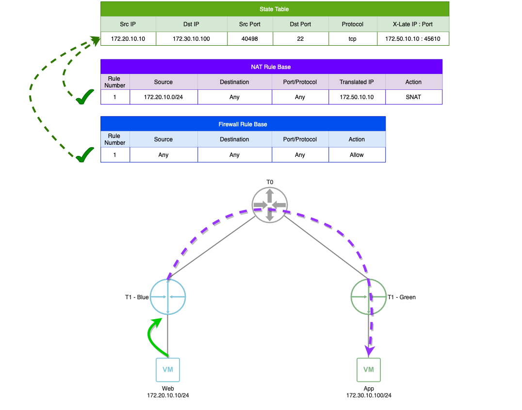
As we previously learned about stateful firewalls, the successful match of new traffic against a rule results in a state table entry. However, since there is both a firewall rule match and a NAT rule match, the end result is a single state table entry that contains all of the data necessary to both match traffic in either direction and to apply any necessary NAT actions.
In the above diagram, we can see the result of matching both of these rules is a state table entry that depicts an ‘X-Late IP: Port‘ field. This demonstrates that any traffic matching this state table entry is not only allowed, but will have a NAT action applied.

In this final diagram, the purple dashed line represents the reply traffic from the ‘App‘ VM back to the SNAT address (‘172.50.10.10‘) used by the ‘T1 Blue‘ SR. Once this packet is received, as it matches an entry in the state table, it is not compared to the NAT or firewall rule base. Additionally, as the matching state table entry has a NAT action included, the packet is “un-SNAT’d” and the destination is changed back to the ‘Web‘ VM’s original IP address of ‘172.20.10.10‘. The packet is then routed to the ‘Web‘ VM.
This is a SNAT example. Is the above applicable to DNAT?
Yes. While we don’t want to belabor the subject by going through it in depth, as DNAT is a stateful service in NSX, everything in the above SNAT example is directly applicable to understanding what happens during a DNAT action, with the key difference being that the expectation with SNAT is it is used on a new session egressing a given SR, while DNAT is intended for use on new traffic as it ingresses an SR.
Next Time…
In both our previous post as well as today’s material, we’ve put a rather heavy emphasis on understanding firewall state and the function it serves when using a stateful NAT service. While we’ve mentioned it several times so far, it’s worth mentioning again that stateful NAT services in NSX are expect the Gateway Firewall to be operating in a stateful manner.
In our next post, we’ll be taking everything we’ve learned thus far and exploring the impact of using stateful NSX NAT services with a stateless Gateway Firewall. Hope to see you there!
