When it comes to utilizing Network Address Translation (NAT) in NSX, configuring NAT can seem both overly simple and extremely complex. In this series, we want to provide an overall look at NAT within NSX by narrowing the scope of conversation to relatively specific use cases in order to better inform on how the solution can be utilized.
Preamble
Before we get started, it’s important to understand the Distributed Router (DR) and Services Router (SR) components of NSX logical routers. Rather than re-invent the wheel, the VMware NSX Reference Design Guide (specifically, sections 4.1.1 and 4.1.2) has a great explanation of DR and SR components, and how they relate.
Next, while we are using NSX 4.1 for this series, we will be using ‘Active-Standby‘ T0s and T1s for stateful services and not the ‘stateful Active-Active‘ model introduced in NSX 4.0.1.1. This is primarily because most users are still using the ‘Active-Standby‘ deployments for stateful services today, and the ‘stateful Active-Active‘ model deserves its own deep dive in the future.
Also, while NAT64 (translating IPv6 addresses to IPv4) is supported on ‘Active-Standby‘ T0s and T1s, we’ll not be discussing this feature. We may come back to it in future posts.
NAT services available in NSX
VMware’s documentation on configuring NAT in NSX is quite robust, depicting the available choices depending on how your logical routers are configured. For our purposes, there are three architectural choices for logical routers and each has a resultant offering of NAT services. These are:
- Active-Active Tier-0 (T0) – supports Reflexive NAT only
- Active-Standby T0 – supports SNAT, DNAT, No-SNAT, No-DNAT, and Reflexive NAT
- Active-Standby T1 – supports SNAT, DNAT, No-SNAT, No-DNAT, and Reflexive NAT
To round out the above, let’s briefly discuss each type of NAT service:
1) SNAT
In reviewing VMware’s documentation regarding SNAT, you may find the following: “NSX SNAT is designed to be applied to traffic that egresses the NSX environment.” This means from a configuration standpoint, the optimal use case for SNAT in NSX is when traffic is outbound from a T1 SR or T0 SR’s Uplink/Service/VTI interface. Let’s take a look at a depiction of a SNAT rule on a T1 SR.
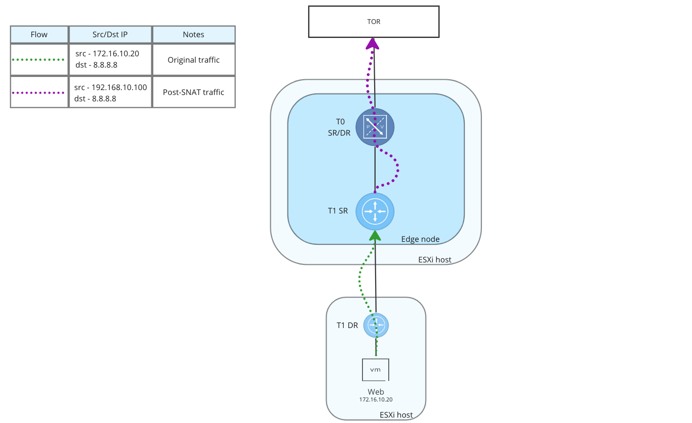
In the above image, the ‘Web‘ VM (IP – ‘172.16.10.20‘) has initiated communication with an Internet address (IP- ‘8.8.8.8‘). Following the green dotted line, we can see this traffic is routed by the T1 DR on the host where the ‘Web‘ vm resides, and is forwarded to the associated T1 SR.
The T1 SR has a SNAT rule configured for this traffic, so the source IP address of the flow is changed to ‘192.168.10.100‘ and the traffic is sent out of the T1 SR’s uplink interface to the T0 (as depicted by the purple dotted line), where it then egresses NSX. As SNAT rules in NSX are stateful, reply traffic will be “un-SNAT’d” by the T1 SR before being returned to the ‘Web‘ VM.
To use SNAT (or DNAT) in your environment successfully, the Gateway firewall function of the SR performing NAT must be enabled with a stateful rule that allows the desired traffic. This could be as simple as the default ‘Any‘ firewall rule on an Active-Standby T0 or T1 or you could create explicit stateful firewall rules allowing this traffic.
Note: While we state that stateful firewall rules are a must, this technically isn’t true; you could use SNAT/DNAT rules in conjunction with No-SNAT/No-DNAT rules to achieve your desired outcome with a disabled or stateless Gateway Firewall. We will be discussing this in-depth in a future post.
2) DNAT
Just as with SNAT, you may find the following about DNAT in VMware’s NAT documentation: “NSX DNAT is designed to be applied to traffic that ingresses the NSX environment.” In other words, DNAT in NSX is optimal for traffic that is external to a given SR (T0 or T1)’s Uplink/Service/VTI interface and is inbound into the NSX environment. Let’s take a look at a typical DNAT flow in NSX:
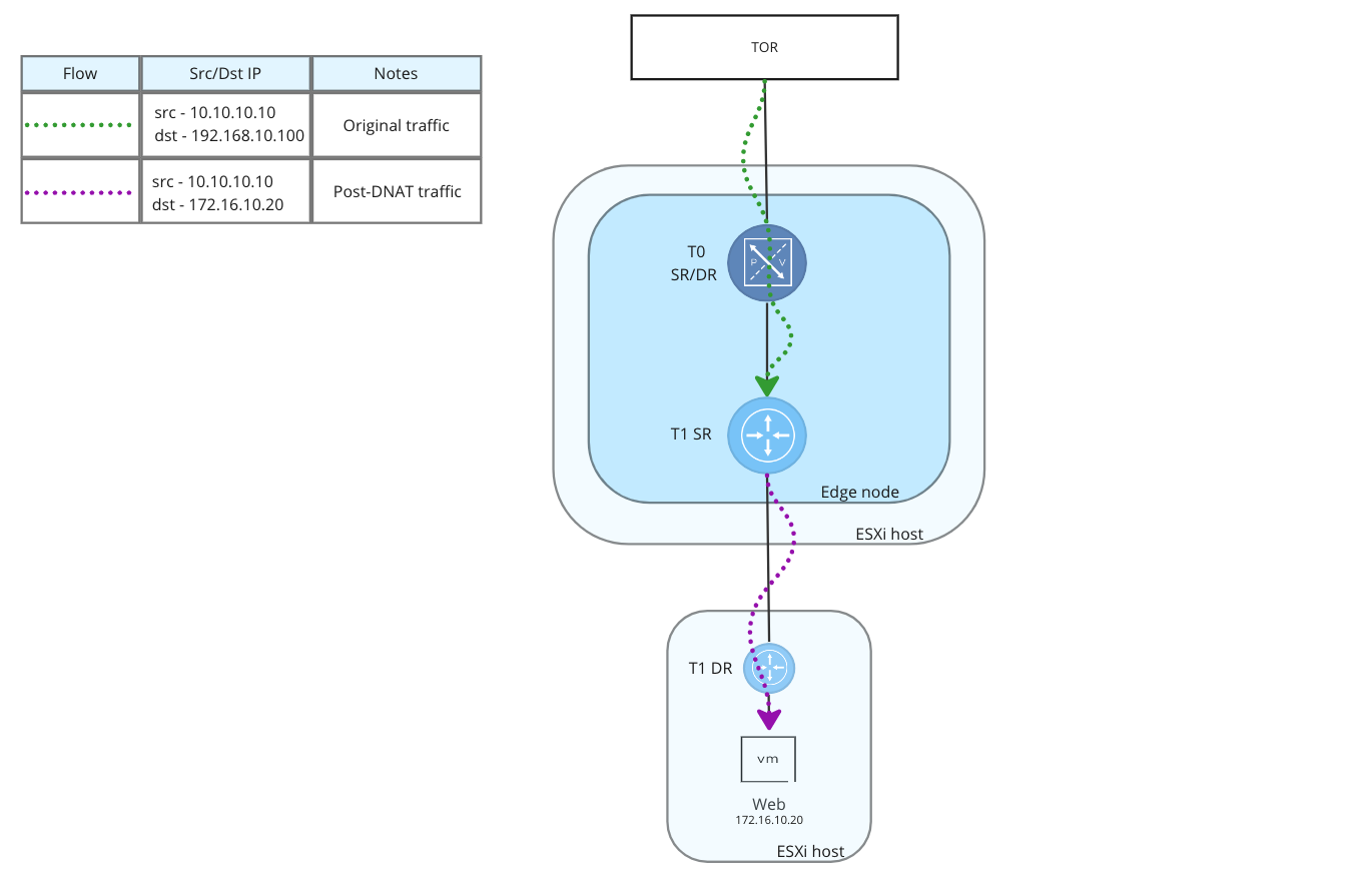
With a DNAT rule, we can take our ‘Web‘ VM, which has an IP address of ‘172.16.10.20‘, and make it available via a different address (‘192.168.10.100‘) to the outside world. In the above image, we can see the original flow in green, and it’s originated from an address that is outside of NSX (‘10.10.10.10‘). As the traffic is delivered to the T0 from the Top of Rack Switch (TOR), the T0 knows this DNAT address is advertised from the T1 SR, and delivers it there accordingly.
At this point, the T1 SR applies the DNAT rule, changing the destination IP address of the flow (in purple) to ‘172.16.10.20‘ before our traffic is delivered to the ‘Web‘ VM. As DNAT rules in NSX are stateful, reply traffic from the ‘Web‘ VM is “un-DNAT’d”, and the requestor (‘10.10.10.10‘) sees replies coming from the DNAT address of ‘192.168.10.100‘.
Note: In the above image, the flow of traffic is depicted leaving the T1 SR and routed to the T1 DR on the ESXi host. In reality, the T1 SR would leverage the T1 DR on the Edge node itself (not depicted) to route the packet to the ‘Web‘ VM; the T1 DR on the ESXi host would not be utilized in this North-to-South flow. We opted not to depict this for simplicity. However, any reply traffic (the ‘Web‘ VM to ‘8.8.8.8‘ ) would utilize the T1 DR on the ESXi host.
3) No-SNAT and No-DNAT
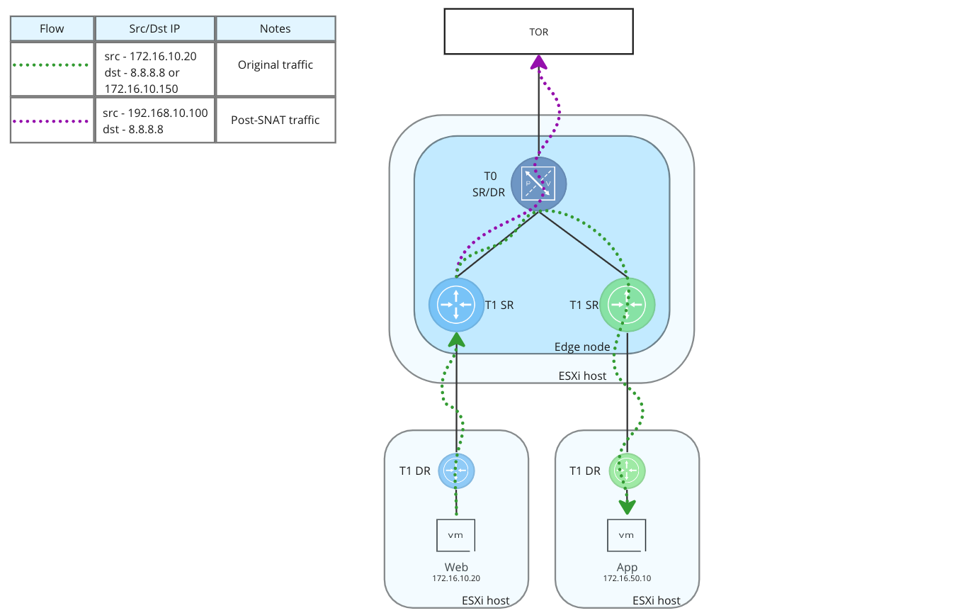
No-SNAT and No-DNAT rules exist to negate existing SNAT and DNAT rules. In the below image, a SNAT rule on the blue T1 SR is configured to NAT the IP of the ‘Web‘ VM (‘172.16.10.20‘) to a new address (‘192.168.10.100‘) when the destination is ‘Any‘. In other words, when traffic from the ‘Web‘ VM leaves the T1 SR for any destination north of the blue T1 SR, the source of the communication is changed from ‘172.16.10.20‘ to ‘192.168.10.100‘.

As in previous SNAT example, traffic from the ‘Web‘ VM destined to an external IP address (‘8.8.8.8‘) operates exactly as it did before; the source of the flow is changed as it egresses the blue T1 SR from the ‘Web‘ VMs original IP address (‘172.16.10.20‘) to the SNAT address of ‘192.168.10.100‘. In the above diagram, you can see the traffic flow represented pre-SNAT by the green dotted line, and post-SNAT by the purple dotted line.
However, the above topology does depict some differences from our previous SNAT example: a green T1 SR and DR along with a VM named ‘App‘( with an IP address of ‘172.16.50.10)’ have been added. Communication between the two VMs begins with the green dotted line, but then changes to a purple dashed line when egressing the blue T1 SR. This purple dashed line demonstrates that traffic from the ‘Web‘ VM will still have its source IP changed to the SNAT IP when accessing the ‘App‘ VM.
In this configuration, communication will work without issue, as traffic can route back and forth successfully, but let’s say new business criteria is introduced that dictates communications between our VMs to must utilize their actual IP addresses. That is, we need to ensure that traffic between the ‘Web‘ and ‘App‘ VMs do not undergo NAT. In order to meet this criteria, we can use a No-SNAT rule.
A No-SNAT rule instructs the T1 SR to not apply SNAT on traffic from ‘Web‘ VM to the ‘App‘ VM. You can see below with a No-SNAT rule configured, traffic from the ‘Web‘ VM to the ‘App‘ VM stays unchanged as represented by the green dotted line. However, all other traffic (in this case, traffic to ‘8.8.8.8‘) still utilizes the original SNAT rule, as demonstrated by the purple dotted line.
As the intent of No-SNAT and No-DNAT rules are to negate existing SNAT and DNAT rules, they typically reside at the top of the NAT rule base. As NAT rules are processed against traffic in order from top to bottom, placing them at the top of the rule base ensures that they match the desired traffic before any SNAT or DNAT rules can. That said, depending on need, you may have No-SNAT and No-DNAT throughout your rule base rather than only at the top.
4) Reflexive NAT
In the prior SNAT and DNAT sections, we noted each is dependent on the state table of the Gateway Firewall for everything to operate as desired. Reflexive NAT differs from this as it’s designed to be utilized without a state table.
A single Reflexive NAT rule created in the NSX UI results in one stateless SNAT rule (applying NAT to “outbound” traffic) and one stateless DNAT rule (applying NAT to “inbound” traffic) on the target T0/T1. As Reflexive NAT doesn’t leverage a state table, all traffic handled by the T0/T1 is continuously evaluated against any Reflexive NAT rules to determine if NAT actions are required.
While you can create Reflexive NAT rules on any T0 or T1 SR, the most prevalent use case in NSX for Reflexive NAT is on an Active-Active T0. As an Active-Active T0 is designed for maximum routing performance, stateful services (such as SNAT and DNAT) are not supported; only Reflexive NAT rules can be utilized when NAT is required.
Configuration Use Cases
In the NAT section of the NSX Administration Guide, you may find a section titled ‘Support Matrices‘ at the bottom of the page. Using this chart, we’d like to take a moment to discuss the types of NAT available for the NAT services listed above. For your ease, we’ll put a copy of the it here:

Each of the NAT services listed in the first column (such as SNAT or DNAT) are then compared to types of NAT to easily identify what each NAT service can do. Let’s review a brief definition of each type of NAT, so you may better understand what a given NAT service can and cannot do:
- 1:1 – This is one-to-one NAT, where a given IP address is always changed into a single different address. ex. 172.16.10.20 is always NAT’d to 192.168.10.100
- n:n – This is a version of many-to-many NAT, where we have a subnet that is changed into a different subnet of an equal size. ex. 172.16.10.0/24 is NAT’d to 192.168.100.0/24
- n:m – Another version of many-to-many NAT, but in this case, the subnets are not of equal size. ex. 172.16.10.0/28 is NAT’d to 192.168.10.0/24
- n:1 – Many-to-one NAT, also called Hide NAT or Port Address Translation, where a given range of IPs or subnet is NAT’d to a single IP address. ex. 172.16.10.0/24 is NAT’d to 192.168.10.100
- 1:m – sometimes called one-to-many NAT, this would occur where a given single IP address could be NAT’d to a range or subnet. ex. 172.16.10.20 is NAT’d to 192.168.100.0/24.
The chart itself is easy to navigate, showing a ‘Yes‘ or ‘No‘ for each match of service and type; the exception being two entries for DNAT which are marked ‘* configurable, but not supported’. Our recommendation would be to treat these as ‘No‘ as well; these configurations may work, but won’t be supported in the event of issues. Also, note the No-SNAT and No-DNAT entries simply show a ‘–‘, as these services exist to exclusively negate SNAT and DNAT.
Next time…
As NAT services in NSX are considered ‘stateful‘ or ‘stateless‘, we will briefly detour our NAT discussion in our next post to explore the conceptual differences between a stateful and stateless firewall. Understanding how these types of firewalls operate is important to our examination of NAT and how they can directly affect NAT functions.
See you there!

Thank you for this great explanation of NSX NAT!
LikeLike
Glad you found it useful!
LikeLike
thank you for this post. it was helpful
LikeLiked by 1 person
I’m glad to hear it helped!
LikeLike