In this final part of our VPN series, we’ll discuss building a VPN over the Internet. More specifically, we will address the impact of Network Address Translation (NAT) on VPN traffic.
Quick Review
In our prior posts, we built Policy Based, Static Route Based, and Dynamic Route Based VPNs. Let’s take a look below at the lab topology from our prior article, which focused on Dynamic Route Based VPNs utilizing BGP to exchange routing information.
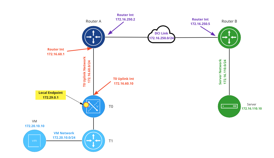
In the above image, the local endpoint in NSX (which resides on a Tier-0 (‘T0‘) Service Router (‘SR‘) ) is configured as ‘172.29.0.1‘, while ‘Router B‘ has a local endpoint matching it’s interface address on the ‘DCI Link‘ (‘172.16.250.5)’. In this example, it’s important to know that each local endpoint can natively be reached by its peer device. That is, the T0 SR can route to ‘172.16.250.5‘, and ‘Router B‘ has a route to ‘172.29.0.1‘.
VPN without NAT
To better understand how NAT can affect our VPN, let’s first establish how an IPSec VPN operates at the networking layer when NAT is not involved. Using the above topology, below is a packet capture performed on ‘Router B‘ before a VPN tunnel has been negotiated. To initiate the VPN, we begin sending pings from the “blue” VM on the NSX side to the “green” server on the ‘Router B‘ side.
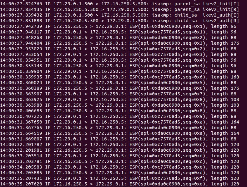
In the first four lines, you can see the VPN tunnel negotiation occurring. Internet Key Exchange (‘IKE‘) communications occur over UDP port 500, and these communications occur between our two local endpoint IP addresses. After tunnel negotiation completes (beginning with line 5), bi-directional encrypted traffic is observed; this is the ICMP echo request and echo reply between the “blue” VM and “green” sever utilizing the VPN tunnel.
If you look closely at the encrypted traffic, you’ll notice there is no port being depicted; you simply see the local endpoint IP addresses communicating with each other, along with a notation of ‘ESP(spi=<hex address>, seq=<hex address>’.
This is because our IPSec VPN is utilizing Encapsulating Security Payload (‘ESP‘), which is IP protocol type ‘50‘. To contrast, TCP is IP protocol type ‘6‘, UDP is type ‘17, and ICMP is type ‘1‘. We will come back to this topic later in our post, but the primary point is to discuss what ESP traffic is and how it looks.
One last thing: For ESP to function properly, a given ESP packet cannot be altered in transit in any way. If this occurs, the receiving side of the ESP traffic (the “other” end of a VPN tunnel) will see the packet has been altered and will reject it. For today’s purposes, understand that ESP traffic may not be directly altered by NAT.
VPN and NAT
Moving on to today’s topic, we will be changing the “rules” of our lab, so to speak. As mentioned above, In prior posts on this topic, each local endpoint of the VPN could successfully route to the other side. ‘Router B‘ had a viable route to ‘172.29.0.1‘, and the NSX T0 SR had a route to ‘172.16.250.5‘.
When building a VPN over the Internet, it’s entirely possible that one or both local endpoints are not assigned publicly routable IP addresses. For today’s blog post, we will pretend that the ‘172.16.250.0/24‘ network (the DCI link) is public IP space, while our local endpoint in NSX is using private IP address space (‘172.29.0.1‘). This means that, while the NSX T0 hosting the local endpoint could certainly route to ‘172.16.250.5‘ using a default route, the inverse is not true; ‘Router B‘ has no route to the “private” IP space of ‘172.29.0.1‘.

In order for our communications to work, we must utilize NAT. As you can see in the above diagram, we have entered a 1-to-1 NAT rule on ‘Router A‘, which changes any communication from ‘172.29.0.1‘ to a “public” IP address of ‘172.16.250.100‘. The inverse of this is true as well; any communication to ‘172.16.250.100‘ will be changed to ‘172.29.0.1‘.
For our VPN to work, ‘Router B’ must point its VPN tunnel’s peer address to ‘172.16.250.100‘ instead of ‘172.29.0.1‘. This allows the VPN communication from ‘Router B‘ to successfully be received by ‘Router A‘, who then performs NAT functions on the traffic before sending it on to the local endpoint on the T0 SR.
As the VPN tunnel’s peer address in NSX is already configured for the “public” IP of ‘Router B‘ (‘172.16.250.5‘), no changes in NSX are required. The default route in NSX will be followed to reach the ‘Router B‘ local endpoint. However, the NAT functions are still applied by ‘Router A‘ as the traffic heads toward its destination of ‘Router B‘, changing the source IP of this traffic from ‘172.29.0.1‘ to ‘172.16.250.100‘.
NAT Traversal
Let’s take a look at a packet capture with the 1-to-1 NAT rule in place on ‘Router A‘. In the below, ‘Router B‘ has already been configured to peer with the NAT address of ‘172.16.250.100‘. Please note additional changes are necessary so the tunnel will come up successfully, and we have already implemented these changes in the below example. We’ll discuss these changes in the next section.
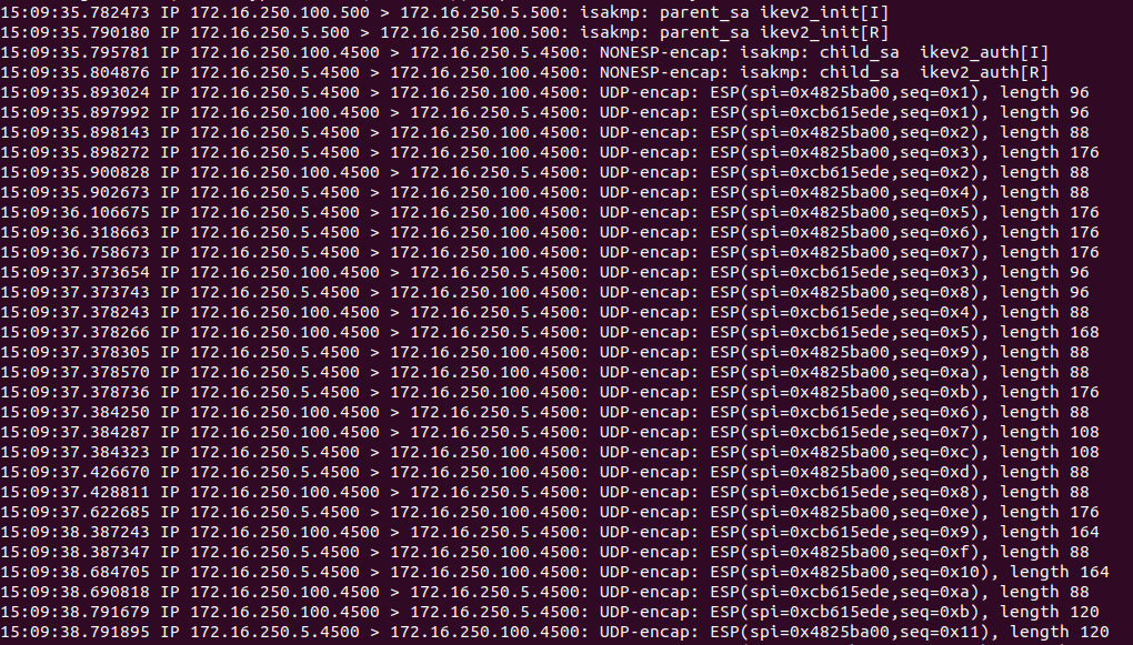
As in our previous capture, IKE negotiation begins using UDP 500. However, a function of modern VPN devices using ESP is the ability to detect if NAT is in use between the local endpoints, and to begin using UDP port 4500 once NAT is detected. This is known as NAT traversal (aka NAT-T).
Lines 1 and 2 show our IKE negotiations beginning using UDP 500, but then we change over to UDP 4500 at line 3, where the IPSec child Security Associations (child-SA)s are being created. Once tunnel negotiation is completed, all ESP traffic is then encapsulated in a UDP port 4500 packet; you may observe this in the above beginning at line 5.
As mentioned above, if NAT is applied to the ESP packet directly, the tunnel would fail as the VPN endpoints would see that the original packet had been “altered”. By encapsulating an ESP packet inside a UDP packet, NAT functions can be applied to outside UDP “wrapper”, leaving the inner ESP packet unchanged.
While a full discussion of NAT-T is outside the scope of this post, we wanted to briefly touch on it as it’s commonly referenced in discussions about applying NAT to VPN traffic. Additionally, we wanted to demonstrate that NSX VPNs are NAT-T compliant.
Initial attempt in Lab with NAT
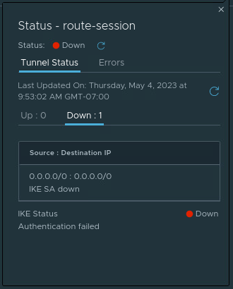
Now that we’ve reviewed a capture where a VPN successfully communicates with NAT involved, let’s investigate the changes that are required, as well as what a failed scenario looks like. To begin, let’s place our 1-to-1 NAT rule on ‘Router A‘, and configure ‘Router B‘ to point to a VPN peer address of ‘172.16.250.100‘. As you can see below in NSX, the tunnel will not come up, and is in a ‘Down‘ state.

If we click on the “I” symbol beside the word ‘Down‘ under ‘Status‘, we can see that the ‘IKE SA‘ is down, and we also see an ‘Authentication failed‘ message under ‘IKE Status‘ at the bottom.
We can also click on the number listed under ‘Alarms‘ (beside the ‘Status‘ column) and get a list of the open alarms for this VPN session. In our lab, we have two alarms listed – ‘IPSec Route Based Tunnel Down‘ and ‘IPSec Route Based Session Down‘. Each of these alarms give a brief description as well as a recommended action.
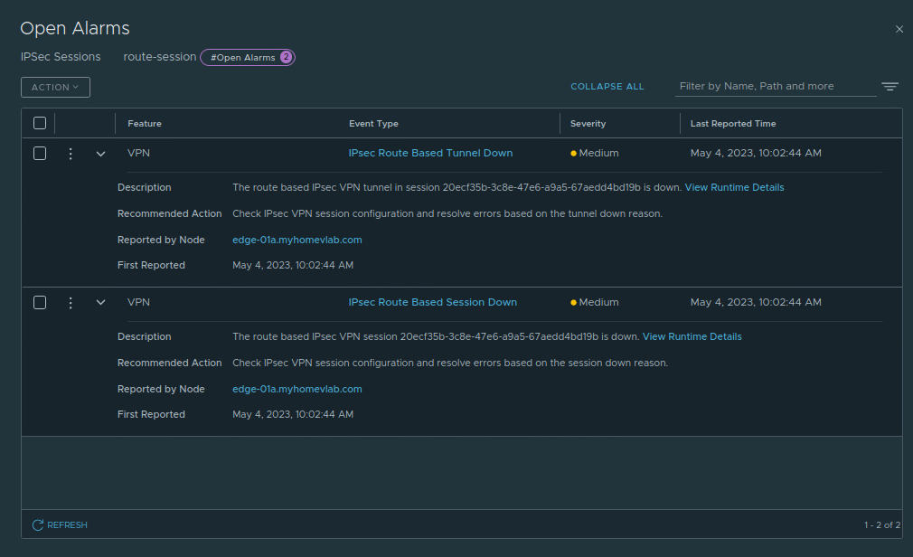
For each alarm, we can click ‘View Runtime Details‘ in the ‘Description‘ field to gather additional information. The ‘IPSec Route Based Tunnel Down‘ alarm (below on the left) notes that the tunnel is down with the reason of ‘IKE SA down‘. When we check the ‘IPSec Route Based Session Down‘ alarm (below on the right), we find the reason of ‘Authentication failed‘.


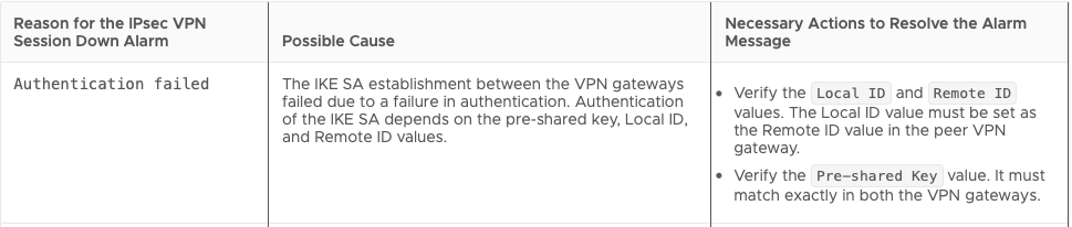
For the ‘Authentication Failed‘ message, we can reference the NSX 4.0 Administration guide for IPSec VPN alarms, along with their possible causes and suggested actions to resolve the issue. Below is a capture of the data from this page regarding ‘Authentication Failed‘.
In our lab environment, we know the only thing that as changed from our previous post is the inclusion of a 1-to-1 NAT rule, and ‘Router B‘ now points to this NAT address (‘172.16.250.100‘) as it’s VPN peer. The Pre-shared Key hasn’t changed and worked in our previous post, so that is not the problem.
However, we never explicitly configured Local ID or Remote ID values in any of our previous posts. In NSX (like many other VPN devices), when a Local or Remote ID is not explicitly configured, these values automatically match the local/remote endpoint IP address. This means in NSX our Local ID is ‘172.29.0.1‘ and the Remote ID for our tunnel is ‘172.16.250.5‘.
On ‘Router B‘, the VPN peer for the tunnel is set to to the 1-to-1 NAT address (‘172.16.250.100‘), with a local ID of ‘172.16.250.5‘. As there’s no explicit Remote ID configured in ‘Router B’s‘ tunnel configuration, the Remote ID defaults to the IP address of the peer, making it ‘172.16.250.100‘.
Remember, ‘Router B‘ is configured to use the 1-to-1 NAT address because the local endpoint in NSX is a “private” IP address of ‘172.29.0.1‘, and is not reachable from the “public” IP space where ‘Router B‘ exists. Using the NAT address ensures that the VPN traffic, including tunnel negotiation, can reach the NSX local endpoint hosted on the T0 SR. However, inside of that actual IKE negotiation traffic, each VPN peer declares their local ID along with the remote ID of the peer.
This means is that the T0 SR receives the IKE traffic after it’s been translated via NAT at ‘172.29.0.1‘, but the actual data inside the IKE traffic clearly states that ‘172.16.250.5‘ (‘Router B’s‘ local ID) wishes to negotiate with a peer using the ID of ‘172.16.250.100‘. The inverse is true as well: ‘Router B‘ expects to receive IKE traffic from a peer ID of ‘172.16.250.100,’ but instead sees a peer id of ‘172.29.0.1‘.
Configuring Local or Remote ID
There’s two ways we can resolve the issue above:
- Configure ‘Router B‘ to use a peer Remote ID of ‘172.29.0.1‘ for the VPN tunnel
- Configure the Local Endpoint utilized by this IPSec Session in NSX with a Local ID of ‘172.16.250.100‘ (the 1-to-1 NAT address)
As this is an NSX blog, we’ll address configuring the Local Endpoint’s Local ID to resolve our problem. Before we do so, please note: a single local endpoint in NSX can be utilized by many different IPSec Sessions. In the scenario where you have existing IPSec sessions, changing the Local ID on the local endpoint utilized by these IPSec sessions requires all remote peers to edit their configurations to utilize this new Local ID. As this would be quite disruptive, we would recommend either having the remote peer configure the Remote ID or create a new Local Endpoint to avoid impacting your existing IPSec communications.
Configuring Local ID in NSX
Configuring a Local ID for a Local Endpoint in NSX is straightforward. First, go to the Local Endpoint in the NSX UI (Networking -> VPN -> Local Endpoints), then click the 3 dots beside the target Local Endpoint and click ‘Edit‘.

In the image above, the IP Address of the Local Endpoint is ‘172.29.0.1’. If you look at the ‘Local ID‘ field, you’ll see the exact same IP address. While we did not configure the Local ID when creating the Local Endpoint, as mentioned above, if the Local ID is not specifically populated, it will automatically be set to the IP address of the Local Endpoint itself.
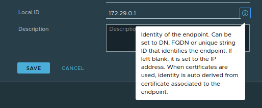
While outside of the scope of today’s discussion, above you can see the data that is provided by clicking the “I” icon’ to the far right of the Local ID field. While the default of a Local ID is the IP address of the Local Endpoint, this field can be configured other various data, such as a DN, FQDN, or a string ID.
For today, we’ll be configuring the Local ID of this Local Endpoint to match the 1-to-1 NAT address (‘172.16.250.100‘) used in our environment. As shown below, once this data is input, click the ‘Save‘ button.

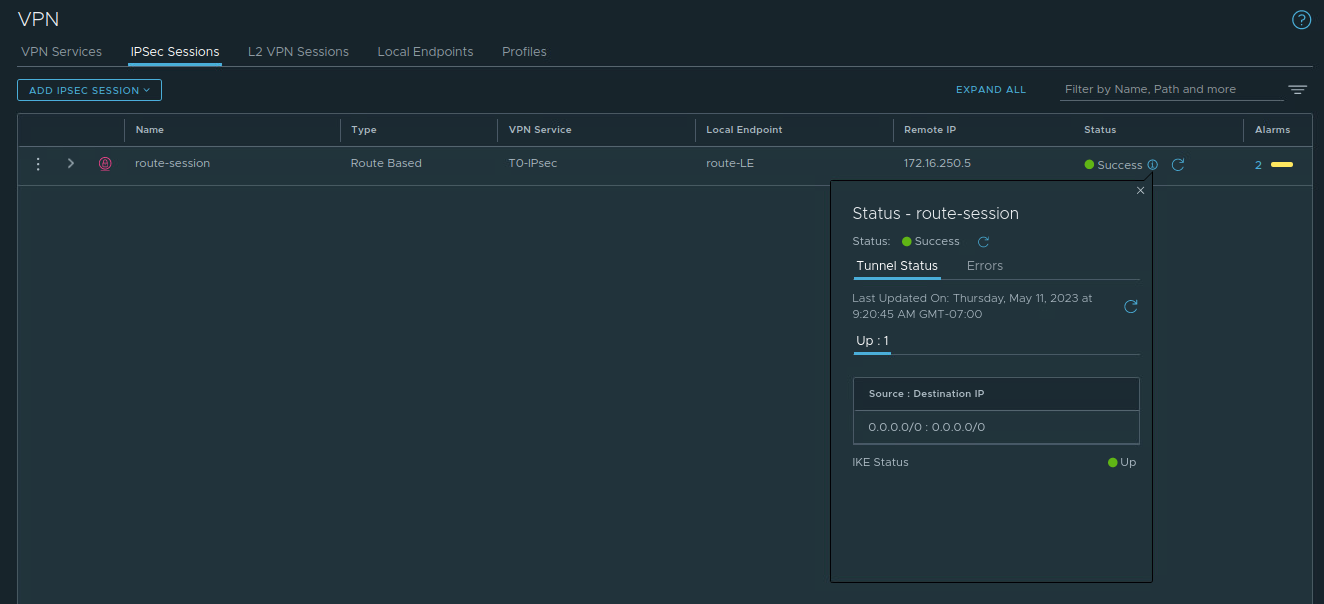
Now, we can return to the ‘IPSec Sessions‘ section of NSX, and we can see our IPSec Session has come up successfully.
Takeaways
The key takeaways from today’s post are:
- ESP is IP protocol type 50
- NAT-T results in ESP packets being encapsulated in UDP port 500 packets to support NAT functions
- The purpose of Local ID and Remote ID and how they can be configured in NSX
This is it for our VPN series. We hope you’ve enjoyed it and maybe picked up a few things. See you next time!
