Since their inclusion in NSX-T 2.5, failure domains are often a topic of discussion during the planning phase of NSX-T deployments. In today’s post, we’ll take a deeper look at failure domains to clarify how they are used and the service they provide.
NSX-T Service Routers
Before we being discussing failure domains, let’s first take a look at the two types of service routers (SRs) available in NSX-T: the Tier-0 (T0) SR and the Tier-1 (T1) SR. If you are using overlay networking via NSX-T today, then you already have T0 SRs, which provide the North/South routing conduit for NSX-T to the physical world.
What’s interesting about T0 SRs is you can easily identify the specific Edge Nodes upon which they reside. As you can see below, when creating ‘External’ interfaces for your T0 Gateway, you must select the specific Edge Node upon which this interface will exist.
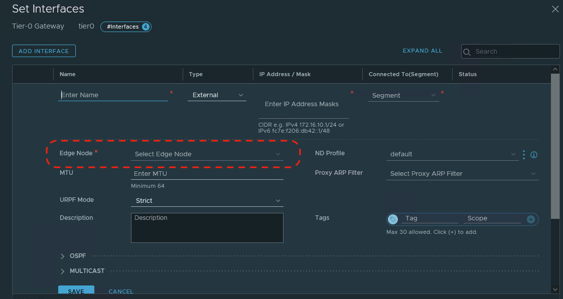
When the first T0 Gateway ‘External’ interface is assigned to an Edge Node, a T0 SR is instantiated. Any additional ‘External’ interfaces created here will be provisioned on the existing T0 SR; remember, an Edge Node may possess only one T0 SR.
In contrast, when creating a T1 SR via Policy Mode, the only choice you must make in regards to Edge Nodes is selecting the Edge Cluster. The creation of a T1 SR results in an “Active” T1 SR and a “Standby” T1 SR which instantiated on two different Edge Nodes in the target cluster.
You may choose to select which Edge Nodes in the target Edge Cluster host the “Active” and “Standby” T1 SRs by utilizing the ‘Set’ option in the T1 configuration. As depicted below, an Edge Cluster named Edge-Cluster has been chosen for the T1, and circled in red is the ‘Set’ option.
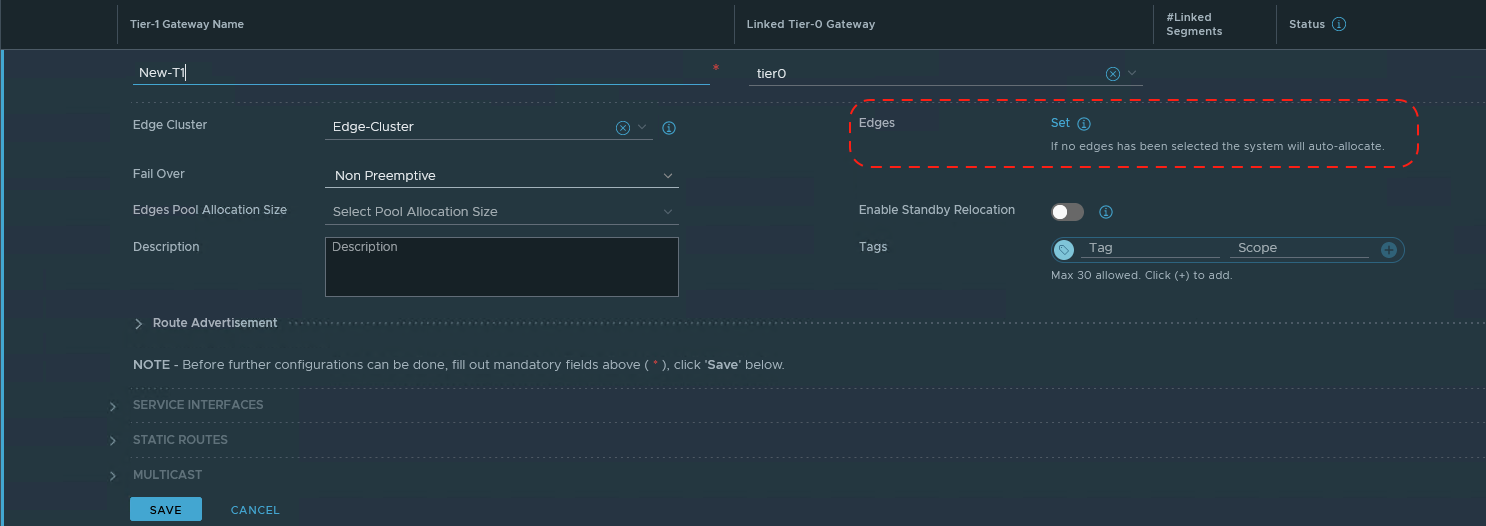
As you can see in the circled section, if you do not manually set the target Edges, the “Active” and “Standby” T1 SRs will be auto-allocated to two Edge Nodes in the selected Edge Cluster.
Service Router deployment
In the diagram below, we have two racks and each rack is comprised of 2 ESXi hosts. We have deployed a single Edge Node to each host, and we’ve created a single NSX-T Edge Cluster containing all four Edge Nodes.

This deployment (Edge Nodes in an Edge Cluster spread among two racks) provides a degree of disaster resiliency. If we lose Rack 1 in the above diagram, we still have the Edge Nodes on Rack 2 providing us with services.
Let’s alter the diagram to focus on the T0 and T1 SRs that reside within the Edge Nodes. Below is an active/standby T0, with the active T0 SR on Edge Node EN01, and the standby T0 SR on Edge Node EN03. This deployment of T0 SRs calls back to the disaster resiliency topic in the previous paragraph; if Rack 1 fails, the standby T0 SR in Rack 2 will become active and continue to provide us with services.

Remember, when creating ‘External’ interfaces for a T0, we select the Edge Node that will host the T0 SR that owns the ‘External’ interface. In the above diagram, we created ‘External’ interfaces for our T0 on Edge Nodes EN01 and EN03, resulting in T0 SRs being instantiated on them. We purposefully chose Edge Nodes EN01 and EN03 as they are deployed in separate racks.
Next, we create two new T1s (Tier1-Blue and Tier1-Green), and assign each to the Edge Cluster, leaving the ‘Set’ option untouched. This action results in our T1 SRs being auto assigned. Tier1-Blue SRs are auto-allocated to Edge Nodes EN02 and EN04, but Tier1-Green SRs are auto-allocated to Edge Nodes EN03 and EN04.
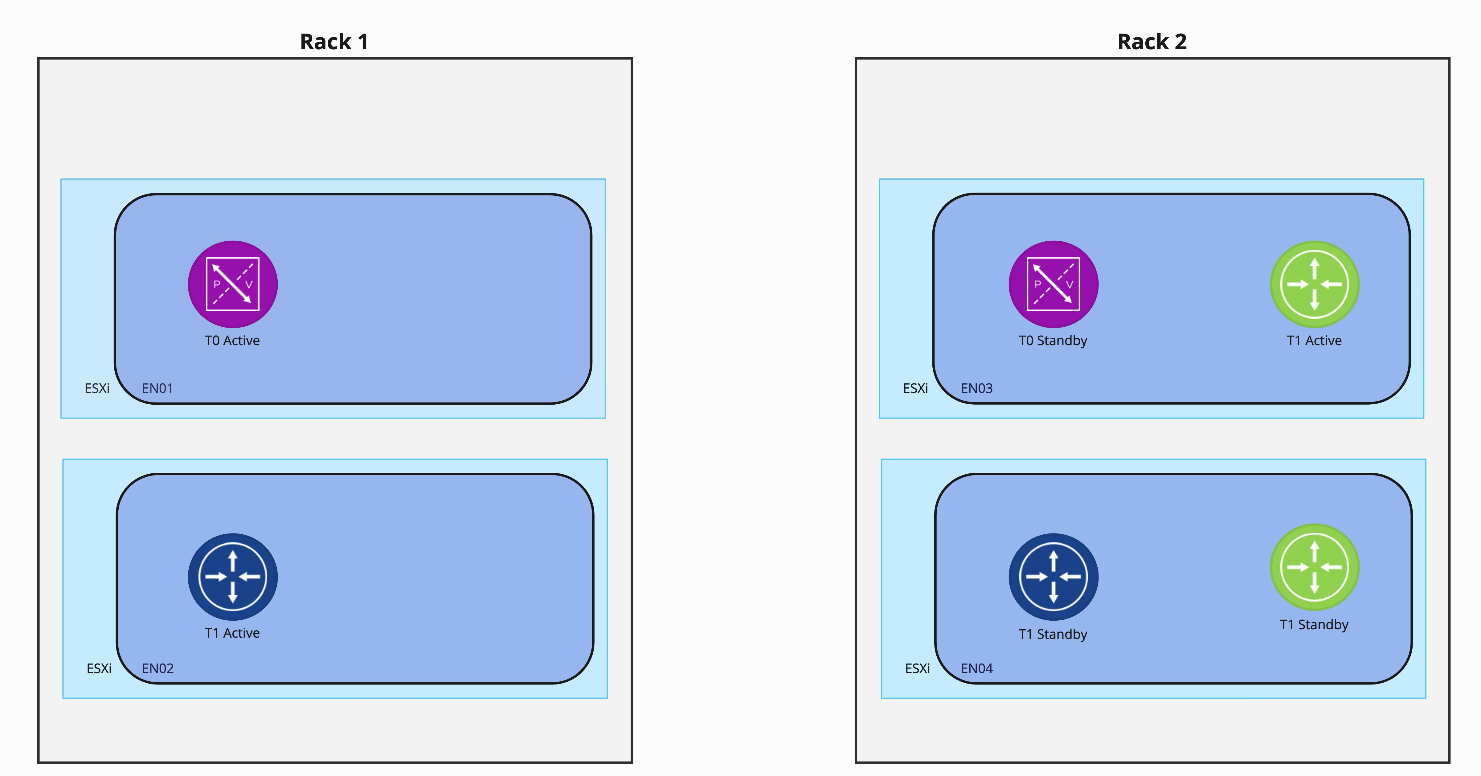
As you can see, the auto-allocation of Tier-1 Green presents a problem. With both Tier-1 Green SRs residing in Rack 2, a full rack failure there would result in the loss of all all Tier-1 Green services.
One method to circumvent this issue is manually selecting Edge Nodes during the Tier-1 creation by utilizing the “Set” function as shown above. This means for every T1 associated with an Edge Cluster, you will manually choose the Edge Nodes which will host the T1 SRs. In the case of the two rack model depicted in our example environment, you are responsible for ensuring the chosen Edge Nodes reside in different racks.
However, a simpler option to achieve these disaster resiliency requirements is utilizing failure domains.
NSX-T Failure Domains
Failure Domains in NSX-T provide the ease of utilizing T1 SR auto-allocation while ensuring each active/standby pair of T1 SRs are deployed according to your disaster resiliency requirements. We will get to the “how” of configuring failure domains later in this post; for now, let’s just observe the service it provides.
Starting over with a 2 rack deployment, we have now created two failure domains, named ‘FD1‘ and ‘FD2‘. FD1 is assigned to the Edge Nodes in Rack 1 and has been configured to host the “active” T1 SRs. FD2 is assigned to the Edge Nodes in Rack 2. Note that all four Edge Nodes here are still in the same Edge Cluster, which is not depicted below.
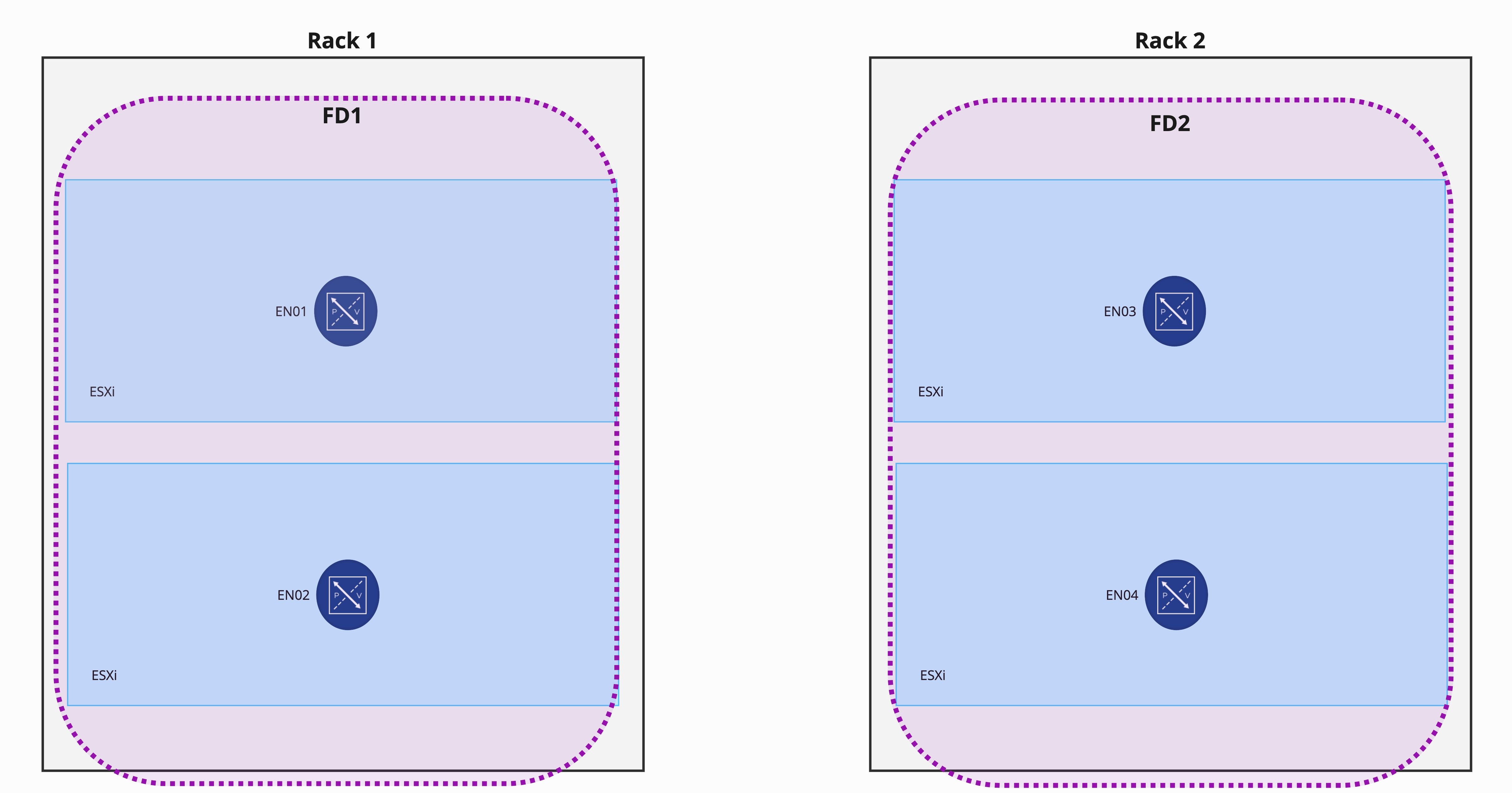
As before, we’ve configured a Tier-0 Gateway in Active/Standby and manually created ‘External’ interfaces on EN01 and EN03. An important item to note here is Tier-0 Gateway SRs do not leverage Failure Domains in any way; Failure Domains exclusively support T1 SR deployments.
With the failure domains configured, we deploy two Tier-1 Gateways that utilize SRs (Tier1-Blue and Tier1-Green) as we did before, leaving the “Set” field untouched.

As you can see, the “active” Tier1-Blue and Tier1-Green SRs have been deployed to Edge Nodes that are members of FD1, while the “standby” SRs have been deployed to FD2. This is because auto-allocation of T1 SRs honor the failure domain configuration that was previously configured.
Rather than being forced to specifically assign the Edge Nodes that each T1 SR will use, instead you configure your failure domains once and then rely on T1 auto-allocation to distribute the T1 SRs according to your disaster resiliency requirements.
Creating Failure Domains
The VMware instructions to create failure domains may be found here in the NSX-T Data Center Multisite documentation. Rather than going through the steps exhaustively, as the existing instructions are more than adequate, we’d like to simply provide some additional context.
Note: You will observe the examples within the NSX-T Data Center Multisite documentation feature failure domains configured between different sites. However, the functionality of failure domains is fully applicable when being used between racks, availability zones, or sites.
The 5 steps to utilize failure domains are:
- Create failure domains
- Create an Edge Cluster
- Associate each Edge Node in the cluster with one of the failure domains
- Configure the Edge cluster to allocate nodes based on failure domain
- Create your T0 and T1 gateways
Steps 1, 3, and 4 above must be completed using the API; you may optionally use the API for steps 2 and 5 (‘Create Edge Cluster’ and ‘Create your T0 and T1 gateways’) or you may elect to use the NSX-T GUI.
If you are inexperienced with using a tool like Postman for API injection, pay special attention to the written directions on step 3 and step 4. In step 3, for each Edge Node:
- Utilize a ‘GET’ to pull the Edge Node information,
- Copy the result of the ‘GET’ into the body of the following ‘PUT’ that will be executed.
- Add the ‘failure_domain_id’ property and the associated failure domain UUID in the body of the ‘PUT’
- Execute the ‘PUT’
Step 4 is functionally the same, except you execute it on the edge cluster itself: Execute a ‘GET’, copy the result into the body of a new ‘PUT’, add the ‘allocation_rules’ property to the body of the ‘PUT’, and then execute. To simplify this step, copy the example ‘allocation_rules’ property that is provided in the NSX-T Data Center Multisite documentation and paste that into the body of the ‘PUT’.
Wrap Up
The key takeaways from this post are:
- Failure domains allow you to deterministically assign active and standby T1 SRs according to your disaster resiliency needs
- Creation of failure domains requires utilizing the NSX-T API (instructions found here)
- Failure domains do not affect T0 SRs; they are used exclusively for T1 SRs.
Well, that’s it for now! On to the next topic!!
