Way back in part three of this series, we discussed the methods available for delivering frames to an NSX bridge when using a VSS/VDS. Out of these methods, the use of ‘Promiscuous mode‘ on a distributed port group (DVPG) for bridging is pretty common, and it’s understandable why: it’s a simple checkbox in the configuration of the DVPG. Once it’s toggled, you find the bridge is up and operational.
However, there’s a best practice when using ‘Promiscuous mode‘ for NSX bridging that is often overlooked, and that’s the enablement of the ‘Net.ReversePathFwdCheckPromisc‘ Advanced System Setting. This setting is configured on the ESXi host where the bridging NSX Edge Node resides.
Rather than simply instruct you to turn on the feature, let’s spend a bit of time today covering what can happen in an environment without ‘Net.ReversePathFwdCheckPromisc‘ enabled.
Lab Environment

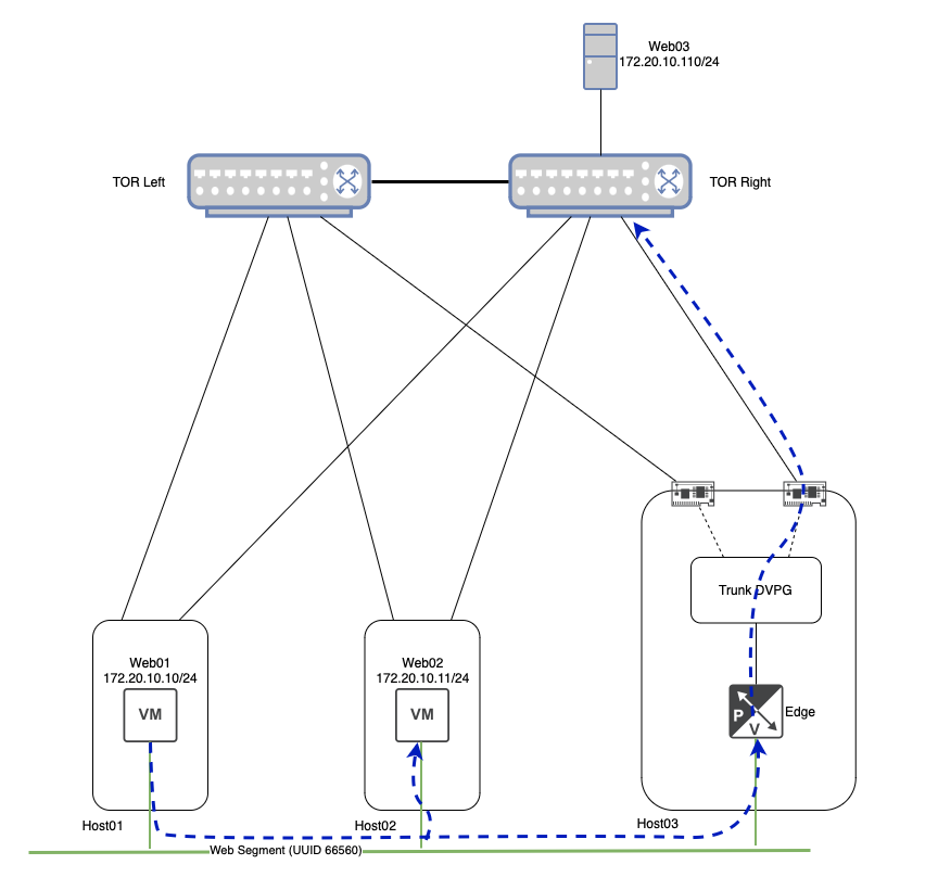
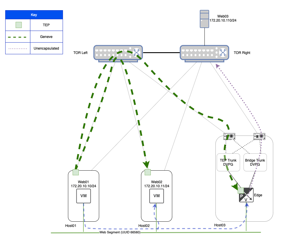
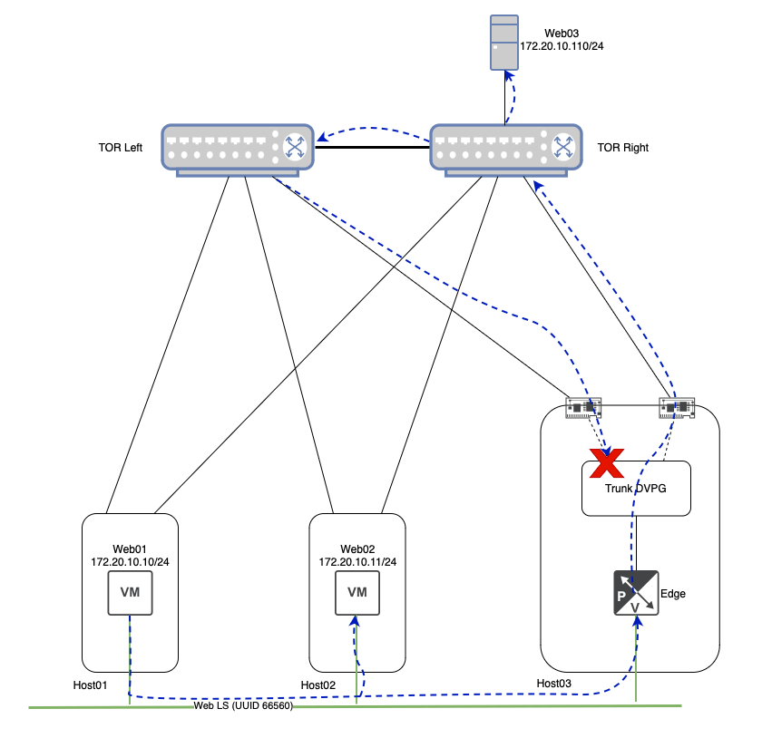
Above you can see the configuration for our lab environment, but let’s do a quick rundown of everything here:
- Three ESXi hosts with two physical uplinks each.
- Each ESXi host has a direct connection to the Top of Rack (TOR) switches (‘TOR Left‘ and ‘TOR Right‘).
- ESXi ‘Host01‘ has a single VM (‘Web01‘), as does ESXi ‘Host02‘ (‘Web02‘).
- ESXi ‘Host03‘ is where the NSX Edge VM that is providing bridging resides.
- ‘Web01‘ and ‘Web02‘ are attached to the ‘Web‘ Segment, which has a UUID of ‘66560‘.
- ‘Web03‘ is a physical server that resides on VLAN ‘110‘, and is directly attached to ‘TOR Right‘.
- The NSX Edge VM is configured to bridge the ‘Web‘ Segment to VLAN ‘110‘. Note that we depict the NSX Edge VM connected to both the ‘Web‘ Segment as well as connected to the ‘Trunk‘ DVPG.
- The ‘Trunk‘ DVPG is configured for VLAN trunking, and has been configured with a range of ‘105-125‘. It is also configured with ‘Promiscuous mode‘ and ‘Forged transmits‘ each set to ‘Accept‘.
- Lastly, the VDS upon which the ‘Trunk‘ DVPG resides is configured with two physical uplinks, and the ‘Trunk‘ DVPG has a teaming of ‘Route based on originating virtual port‘, with both uplinks marked as ‘Active‘.
You may have noticed that ‘Host03‘ is larger in depiction than ‘Host01‘ or ‘Host02‘, and possesses icons for its physical NICs. This is a deliberate choice, as the utilization of a host’s physical NICs by the ‘Trunk‘ DVPG plays a large part in today’s discussion.
Note: For simplicity in the following section (‘Broadcast Traffic and Bridging‘), we’ll not be depicting the encapsulation/decapsulation of Geneve flows for traffic traversing the ‘Web‘ Segment. This is because our focus is largely on the VLAN side of the bridge, and trying to depict the Geneve flows between ESXi hosts and the Edge Node would make for a far busier diagram. For the moment, we will be depicting traffic traversing the ‘Web‘ Segment logically (using the green line at the bottom of the diagram), rather than literally (which would require showing the Geneve flows between each host/Edge via the TOR switches).
Broadcast Traffic and Bridging
In the above, ‘Web01‘ wishes to initiate communication with ‘Web03‘. Lacking the MAC address of ‘Web03‘, ‘Web01‘ broadcasts an ARP Request frame. As ‘Web03‘ does not directly reside on the ‘Web‘ Segment itself (remember, ‘Web03‘ is a physical server on VLAN ‘110‘), the NSX Central Control Plane (‘CCP‘) will not have a record of ‘Web03‘s IP or MAC address.
This means that NSX must replicate this broadcast frame to all TEPs via Geneve that posses VMs (or bridges) attached to the ‘Web‘ Segment. ‘Host02‘ gets a copy of the broadcast frame, and passes it onto ‘Web02‘. A Geneve packet containing the ARP request is also sent directly to the TEP of the NSX Edge VM, as it is bridging the ‘Web‘ Segment to VLAN ‘110‘.
The NSX Edge bridge receives the frame on the ‘Web‘ Segment, 802.1q tags it with VLAN ‘110‘ (aka VLAN tagging), and forwards it out its interface to the ‘Trunk‘ DVPG. As mentioned previously, the ‘Trunk‘ DVPG is configured to support VLANs ‘105-125‘, so it accepts this frame without issue. As the ‘Trunk‘ DVPG is configured with the ‘Route based on originating port‘ teaming policy, it has chosen to send the frame out of ‘uplink-2‘, which is directly connected to ‘TOR-Right‘.
Note: Since the ‘Trunk‘ DVPG is set to ‘Accept‘ for ‘Forged Transmits‘, the frame sent from the ‘Web01‘ VM is accepted without issue, even though it’s MAC address is clearly not the same as the interface of the NSX Edge VM. You can read more about the behavior of Forged Transmits in our previous post on the topic.
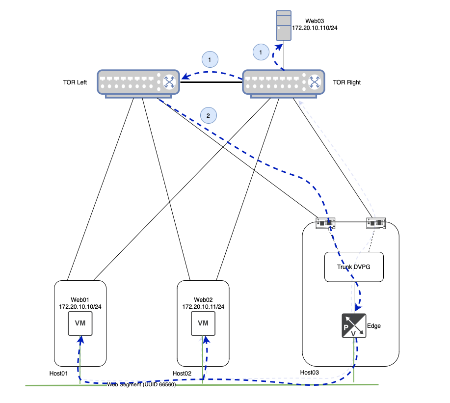
Continuing to follow the ARP Request frame, ‘TOR Right‘ delivers the frame to ‘Web03‘ as the switch port is a member of VLAN ‘110‘. However, recall that a physical switch will (correctly) forward a broadcast frame to any port that is a member of the associated VLAN. In our case today, this means that this same broadcast frame is also sent across the inter-switch link between ‘TOR Left‘ and ‘TOR Right‘.
Now that ‘TOR Left‘ has received the broadcast frame, it too will send the frame to any ports that are members of VLAN ‘110‘. As you can see above, this includes the link from ‘TOR Left‘ to ‘Host03‘. To recap, our initial ARP request has left ‘Host03‘ via ‘uplink-2‘ to ‘TOR Right‘, and has now made it’s way back to ‘Host03‘ via it’s ‘uplink-1‘ connection to ‘TOR Left‘.
Once it’s received by ‘Host03‘, the frame is handed to the ‘Trunk‘ DVPG. As the ‘Trunk‘ DVPG has ‘Promiscuous Mode‘ set to ‘Accept‘, the frame is received by all members of the DVPG, regardless of the destination MAC address.
Upon receiving the VLAN ‘110‘ tagged frame, the NSX Edge bridges the frame back onto the ‘Web‘ segment, where it is sent to all attached VMs. In our small lab environment, this means ‘Web01‘ and ‘Web02‘ each receive this frame.
On the surface, this seems innocuous. While it’s certainly inefficient for the ARP request to make a single loop, there isn’t an obvious negative effect upon the VMs themselves; the ARP Request frame still has a source of ‘Web01‘s MAC address, so it’s not like ‘Web02‘ or ‘Web03‘ could potentially learn any misinformation.
However, now that we understand the packet flow itself in this scenario, let’s briefly discuss how TEP to TEP communications in NSX work, and how this looped broadcast frame can give us some real trouble.
Host TEP to Host TEP Communication
When two VMs attached to the same NSX Overlay segment communicate, presuming the VMs are on different hosts, their traffic is encapsulated in the Geneve protocol by their ESXi hosts. The hosts in this communication flow encapsulate the traffic utilizing a VMK interface called a TEP, which stands for Tunnel End Point. Let’s take a quick look at how ‘Web01‘ and ‘Web02‘ communicate via their host’s TEP interface.

Above we can see any communication between ‘Web01‘ and ‘Web02‘ is taken by the ESXi host upon which they reside and encapsulated in Geneve via their local TEP interface. The Geneve traffic is then sent to the destination ESXi’s TEP interface, where it is decapsulated and delivered to the destination VM.
In our lab, ‘Host01‘ possesses two TEPs for Overlay traffic (one for each physical NIC), and each TEP possesses an IP address: ‘172.16.40.14/24‘ and ‘172.16.40.15/24‘. The TEPs for ‘Host02‘ have the IP addresses of ‘172.16.40.10/24‘ and ‘172.16.40.11/24‘. With this info in mind, let’s look at the MAC address table for the ‘Web’ overlay segment to which ‘Web01‘ and ‘Web02‘ are attached.
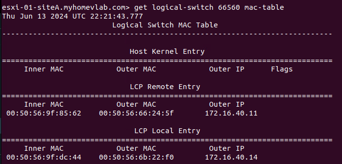
On ‘Host01‘ above, we can see the results of executing the ‘get logical switch <UUID> mac-table‘ command for the target segment of ‘66560‘, which is the UUID of the ‘Web‘ segment. The data is functionally broken down into three sections:
- Host Kernel Entry
- LCP Remote Entry
- LCP Local Entry
At this point, ‘Web01‘ and ‘Web02‘ have not communicated directly. As such, there are no entries under the ‘Host Kernel Entry‘ section (we’ll talk more about this later). At the bottom of the image, we can see there’s a single entry under ‘LCP Local Entry‘. Entries in this section detail the MAC addresses of VMs that reside on this host and are attached to the target logical switch. Our single entry lists three items:
- Inner MAC – this is the MAC address of the VM itself
- Outer MAC – this is the MAC address of the TEP that will be responsible for Geneve traffic for this VM
- Outer IP – this is the IP address of the TEP that will be responsible for Geneve traffic for this VM
This means for ‘Host01‘, traffic to and from the ‘Web01‘ VM (which has the MAC address of ‘00:50:56:9f:dc:44‘) will utilize the ‘172.16.40.14‘ TEP. As an aside, it’s worth mentioning that ‘LCP‘ stands for ‘Local Control Plane‘.
You’ll also see there’s a single entry in the ‘LCP Remote Entry‘ section. Entries here typically represent other VMs that are attached to the target segment that reside on other hosts. In our lab, ‘Web02‘, which resides on ‘Host02‘, is also a member of the ‘Web‘ segment. This entry demonstrates the NSX CCP has pre-populated ‘Host01‘ with the MAC address of ‘Web02‘ (listed under ‘Inner Mac‘ with a value of ‘00:50:56:9f:85:62‘) and the TEP on ‘Host02‘ (listed under ‘Outer Mac‘ and ‘Outer IP‘) that will be utilized for Geneve traffic destined for ‘Web02‘.

Above we can see the output of the same command on ‘Host02‘. Note that it’s the same data, but transposed. Now, the information for ‘Web02‘ is listed under ‘LCP Local Entry‘, while the information to reach ‘Web01‘ resides under ‘LCP Remote Entry‘.
We will now have ‘Web01‘ ping ‘Web02‘. When this action is initiated, note the new line under Host Kernel Entry on ‘Host01‘ in the below image when running the ‘get logical-switch‘ command again. This information is nearly identical to the data in the ‘LCP Remote Entry‘ field, aside from a new column called ‘Flags‘.
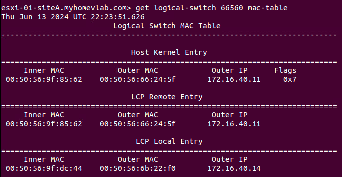
Host Kernel Entry on Host01
Data listed in the ‘Host Kernel Entry‘ section are functionally data plane learned TEP entries. That is, while the ‘LCP Remote Entry‘ table demonstrates the NSX CCP provided information to reach ‘Web02‘, the entry listed under ‘Host Kernel Entry‘ shows that traffic was actually received from ‘Web02‘ via ‘Host02‘s TEP. Understanding that entries under ‘Host Kernel Entry‘ are learned via received traffic will become important shortly.
Below is the output of the same command from ‘Host02‘. All the data here (including the item under ‘Host Kernel Entry‘) is transposed from the data listed on ‘Host01‘. The information below shows that traffic was actually received from ‘Web01‘ via ‘Host01‘s TEP.
Host TEP to Edge TEP Communication
Like communication between Host TEPs, when traffic from a VM on a Host needs to reach an NSX Edge, Geneve encapsulated packets are sent between the Host TEP and the Edge Node TEP. This is an important item to remember: NSX Edge Nodes possess their own TEP interfaces. When using an Edge Node VM, Geneve traffic from an ESXi TEP destined to the Edge VM TEP does not utilize the TEPs on the ESXi host where the Edge Node VM resides; the traffic is passed directly to the Edge Node VM’s TEP.
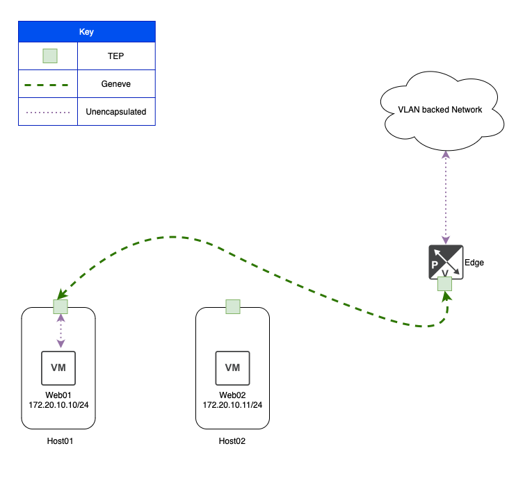
In the above, we can see that ‘Web01‘ is communicating to a VLAN backed network via an NSX bridge. This is made possible by ‘Host01‘ encapsulating ‘Web01‘s traffic in Geneve and sending it via its own TEP to a TEP on the bridging NSX Edge VM.
In our lab environment (with the NSX bridge enabled), if ‘Web03‘ needs to communicate with either ‘Web01‘ or ‘Web02‘, presuming ‘Web03‘ does not already know their MAC addresses, it must first broadcast an ARP request. The effect of ‘Web03‘ sending this traffic is below: Both ‘Host01‘ and ‘Host02‘ have learned the MAC address of ‘Web03‘ (which is ‘00:50:56:90:11:53‘) as demonstrated in the ‘Host Kernel Entry‘ section under ‘Inner MAC‘.
You may also notice the ‘Outer IP‘ field is populated with the IP address of the NSX Edge’s TEP, which is ‘172.16.50.16‘. This means that now both ‘Host01‘ and ‘Host02‘ know to reach ‘Web03‘ via the Edge VM TEP.
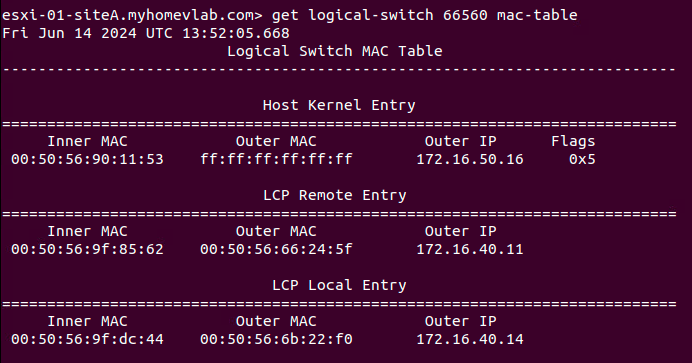

Note: For the ‘Web03‘ entry under ‘Host Kernel Entry‘ in both of the above examples, the ‘Outer Mac‘ field is ‘ff:ff:ff:ff:ff:ff‘; this is because the TEPs for our ESXi hosts are in the ‘172.16.40.0/24‘ subnet, while the Edge TEP is using an IP from the ‘172.16.50.0/24’ subnet. This means that traffic from Host TEPs to Edge TEPs in our lab must be routed. If we had configured our Host TEPs and Edge TEPs to be in the same subnet (which requires additional configuration considerations), then you’d see the actual MAC address of the Edge Node TEP listed under ‘Outer MAC‘.
Back to the issue at hand…
So now that we have a base understanding of how our MAC tables on a logical switch look, let’s review the effect of a looped broadcast frame in our lab topology. To start again, ‘Web01‘ sends an ARP request for the IP address of ‘Web03‘, which is ‘172.20.10.110/24‘.
This is a slightly altered diagram of what was shown in the ‘Broadcast Traffic and Bridging‘ section. At the bottom, we still show the logical flow of the broadcast ARP frame being delivered to all members of the ‘Web‘ Segment via the blue dashed line. However, in this depiction, we also show the actual Geneve traffic flow via the green dashed lines. Here we see the broadcast ARP request results in a Geneve frame sent from the TEP on ‘Host01‘ to the TEP on ‘Host02‘, and another Geneve frame from the ‘Host01‘ TEP to the Edge VM TEP that is bridging the ‘Web‘ Segment.
If you look at ‘Host03‘, you’ll see that we now depict two different DVPGs: One named ‘TEP Trunk‘ and the other named ‘Bridge Trunk‘. In our configuration, the interface on the Edge VM where the Edge’s TEP resides is attached to the ‘TEP Trunk‘ DVPG, while the Edge VM interface that is used to reach the VLAN side of the bridge is connected to the ‘Bridge Trunk‘ DVPG.
Note: We certainly could have used the same DVPG to do both, but separating them allows for a simpler diagram to depict what is happening. In a real world environment, it also would allow for direct control of which pNICs on an ESXi host would be utilized for the TEP side of the traffic versus the VLAN side of the bridge, if so desired.
Once the Geneve encapsulated broadcast frame arrives at the Edge VM’s TEP, it is decapsulated and bridged to VLAN ‘110‘, as shown via the purple dotted line, where it is sent onward to ‘TOR Right’.

The above image shows the broadcast ARP frame being sent from ‘TOR Right‘ to ‘TOR Left‘ (as well as being delivered to ‘Web03‘), and then back to ‘Host03‘, just as described in the ‘Broadcast Traffic and Bridging‘ section. Since the ‘Bridge Trunk‘ DVPG has ‘Promiscuous Mode‘ configured to ‘Accept‘, the frame is delivered to the connected interface of the Edge VM.
While we again show the logical delivery of the looped broadcast frame to ‘Web01‘ and ‘Web02‘ via the dashed blue line at the bottom, it’s more important to direct our attention to the Geneve traffic. Above we can see that the Edge VM TEP must send a Geneve packet to the TEPs on both ‘Host01‘ and ‘Host02‘ as the looped ARP broadcast frame must be delivered to all members of the ‘Web‘ Segment.
So what can go wrong?
As you can see from our previous data, when ‘Web01‘ sends a broadcast packet (in our case, an ARP request) for a device that is across the bridge, any host that has a VM attached to the ‘Web‘ Segment will see this same broadcast ARP packet twice:
- When ‘Web01‘ sends the initial ARP request
- When the broadcast frame is looped back from the physical world via the Edge VM bridge
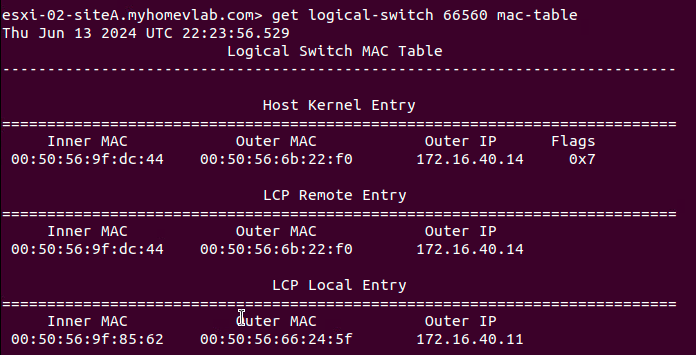
Let’s take a look at the Mac-table for our segment on ‘Host01‘ and ‘Host02‘ again now that the broadcast ARP frame has been looped. First, let’s look at ‘Host01‘:
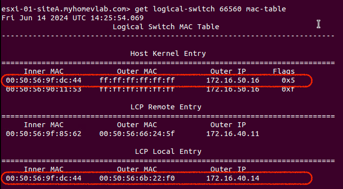
Hmm… so this appears unusual. We still see the MAC address for ‘Web01‘ in the ‘LCP Local Entry‘ as expected. However, there’s also an entry for the MAC address of ‘Web01‘ in ‘Host Kernel Entry‘ table and its ‘Outer IP‘ field is using the IP address of the Edge Node TEP.
This is because ‘Host01‘ received the looped broadcast ARP frame (which originated from ‘Web01‘) via a Geneve encapsulated packet from the Edge VM TEP. As such, ‘Host01‘ has entered the relevant data as an item under the ‘Host Kernel Entry‘ table, just like it would any other Geneve encapsulated packet.
While this does have an unsettling appearance, ‘Host01‘ possessing a ‘Host Kernel Entry‘ for ‘Web01‘s MAC address and the Edge VM’s TEP MAC/IP does not have any ill effects on its own of which we are aware.
With that being said, let’s look at Host02, and see how it appears:

‘Host02‘ still has one ‘LCP Local Entry‘ for ‘Web02‘, so no issue there. However, take a look at the single entry in the ‘LCP Remote Entry‘ table and compare it to the single entry in the ‘Host Kernel Entry‘ table. ‘Host02‘ still has an ‘LCP Remote Entry‘ item for ‘Web01‘ as it should, but upon receiving the looped broadcast ARP frame (which was wrapped in a Geneve header sourced from the Edge VM TEP), ‘Host02‘ now has an entry to reach the MAC address of ‘Web01‘ via the Edge TEP’s IP address of ‘172.16.50.16‘.
Entries in the ‘Host Kernel Entry‘ table are honored before entries in the ‘LCP Remote Entry‘ table. This means that, for now, ‘Host02‘ has incorrectly learned to reach ‘Web01‘ via the Edge Node TEP. When ‘Web02‘ attempts to communicate with ‘Web01‘, ‘Host02‘ will send this traffic via Geneve to the Edge Node TEP. To demonstrate this, we’ll now have ‘Web02‘ attempt to ping ‘Web01‘:
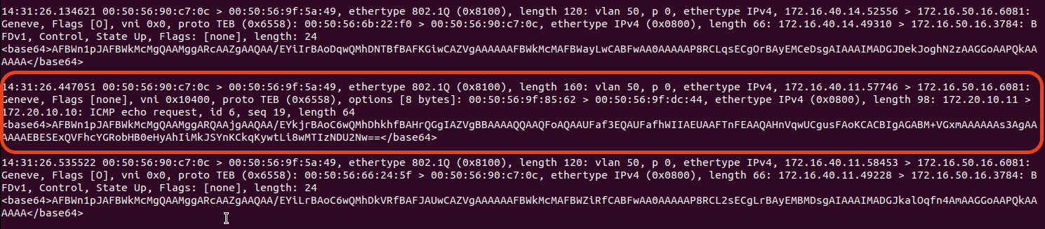
The above was captured on the Edge Node’s TEP interface. While there’s a lot of extraneous traffic that runs to and from the TEP, let’s look at the circled data. You can see that the Geneve header itself is sourced from ‘172.16.40.11‘ (‘Host02‘s TEP) and is destined for the Edge VM’s TEP (‘172.16.50.16‘). If you look a bit deeper in the frame, you can see the inner header, with a source of ‘172.20.10.11‘ (‘Web02‘) and a destination of ‘172.20.10.10‘ (‘Web01‘). You can even see this is an ICMP echo request.
Once received by the Edge VM TEP, this frame will be bridged to VLAN ‘110‘ and, ultimately, go nowhere.
This phenomenon typically results in intermittent connectivity issues. At this point, ‘Host01‘ still knows how to communicate with ‘Host02‘ properly. If ‘Web01‘ sends a frame to ‘Web02‘, ‘Host02‘ will overwrite the incorrect entry in its ‘Host Kernel Entry‘ table with the proper one from ‘Host01‘. This can make troubleshooting difficult as by the time you start gathering diagnostic data, the incorrect ‘Host Kernel Entry‘ might have already been overwritten with a good entry, or it may have idle timed out and been removed.
How to prevent this issue
Luckily, preventing this entire issue is quite easy. As mentioned in the onset of this post, we simply enable the ‘Net.ReversePathFwdCheckPromisc‘ Advanced System Setting on any ESXi host where a bridging NSX Edge VM may reside.
In vCenter, we can select a target host (in our lab, this would be ‘Host03‘, where our Edge VM resides), and go to Configure -> System -> Advanced System Settings. From here, click the ‘Edit‘ button at the top right, and filter the ‘Key‘ column with the phrase “promisc“. This will result in a single entry appearing, which is the ‘Net.ReversePathFwdCheckPromisc‘ setting. Change the value from “0” to “1” and hit ‘OK‘ at the bottom.
Ensure this is done on any host that could host a bridging Edge VM. For a typical bridge deployment, you have an Active/Standby Edge VM pair. If these Edge VMs can exist on any host in a given vSphere cluster, then all the hosts in that cluster should receive the above change.
Once you’ve made this change to all target ESXi hosts, you’ll need to edit the DVPG that is providing access to the bridged VLAN networks (this is where ‘Promiscuous mode‘ is configured). In the Security settings of the DVPG, set ‘Promiscuous mode‘ to ‘Reject‘, hit ‘OK‘, then make this same change again, setting ‘Promiscuous mode‘ back to ‘Accept‘. Hit ‘OK‘ one final time your changes are now complete. In short, you’ll turn ‘Promiscuous mode’ off and on again to enforce the ‘Net.ReversePathFwdCheckPromisc‘ changes. The result of this change is demonstrated below:
As you can see above, when the broadcast frame loops around to ‘TOR Left‘ from ‘TOR Right‘, and is ultimately delivered to the ‘Trunk DVPG‘, the ESXi host (‘Host03‘) recognizes that this same frame was already sent out via the ‘Trunk DVPG‘, and properly drops it. Now there’s no loop, and therefore, the issue described in this post has been nullified!
A final note regarding ARP in NSX…
In our topic today, we demonstrated the effect of ARP broadcast traffic on NSX bridging in conjunction with ‘Promiscuous mode‘ on a DVPG. While any broadcast traffic can cause this issue, ARP is going to be used in any IPv4 environment, so that’s why we opted to focus on it.
That being said, there’s a notion that “ARP suppression” in NSX should prevent this issue. It’s worth mentioning that while NSX absolutely does have ARP suppression functionality, it only applies to ARP traffic where NSX knows the MAC address and IP address of a VM attached to a segment. NSX can learn this information via methods such as ARP Snooping, DHCP Snooping, and VMware Tools among others ( all of these options are enabled by default, and can be configured via ‘Segment IP Discovery Profiles‘.)
However, NSX is not natively aware of the MAC/IP associations of devices on the bridged VLAN. This means a VM on an NSX segment must learn MAC address of a device on the bridged VLAN via standard broadcast ARP requests. In our lab, NSX doesn’t know the IP/MAC address of ‘Web03‘ in order to perform ARP suppression, so it is forced to broadcast ‘the ‘Web01‘s ARP request frame to all members of the ‘Web‘ segment.
Wrap Up…
The real takeaway is if you are going to use a DVPG configured for Promiscuous Mode for NSX Bridging, ensure that you enable ‘Net.ReversePathFwdCheckPromisc‘ on the ESXi hosts where the bridging NSX Edge Node may reside. Ultimately, everything else was a deep dive to fully explain “why” enabling ‘Net.ReversePathFwdCheckPromisc‘ is a best practice for this particular NSX bridging architecture. Nonetheless, we hope you found it useful!
