In our previous post, we created a route based VPN utilizing static routes on a Tier-1 (T1) Service Router (SR). Today, we will demonstrate how to utilize route-based VPNs via Dynamic Routing.
Dynamic Routing and VPNs
In the introduction to our VPN series, we provided a flowchart identifying where a given type of VPN (either Policy or Route Based) could be utilized. A key piece of data identified in the flowchart is: a route based VPN terminated on a T1 SR may only utilize static routing.
In NSX, only Tier-0 (T0) SRs provide dynamic routing protocol communications utilizing BGP over a VPN (OSPF is not supported). Additionally, the T0 must be operating in ‘Active/Standby‘ HA mode.
Before we begin…
Today’s lab topology is identical to the prior Route Based VPN post, with the exception of the configuration on ‘Router B‘, which you’ll find below:
set policy access-list 10 rule 10 action 'permit'
set policy access-list 10 rule 10 source inverse-mask '0.0.0.255'
set policy access-list 10 rule 10 source network '172.16.110.0'
set policy route-map allow-vpn rule 10 action 'permit'
set policy route-map allow-vpn rule 10 match ip address access-list '10'
set policy route-map allow-vpn rule 20 action 'deny'

set protocols bgp 210 address-family ipv4-unicast redistribute connected
set protocols bgp 210 neighbor 10.5.6.7 address-family ipv4-unicast route-map export 'allow-vpn'
set protocols bgp 210 neighbor 10.5.6.7 remote-as '100'
Above is an access-list and a route-map that ensure only the desired network on the ‘Router B‘ side is advertised (‘172.16.110.0/24‘). The route-map is applied to the BGP neighbor ‘10.5.6.7‘, which is the VTI on the NSX side (we discuss more about this below).
An additional change from the previous article – we have removed the static route entry on ‘Router B‘ for the ‘172.20.10.0/24‘ network with a next-hop of ‘10.5.6.7‘. BGP will be utilized to learn this same route once today’s configuration is complete.
Configuring an IPSec Dynamic Route Based VPN
From an NSX perspective, there’s little difference in configuring a dynamic route based VPN vs a static route based VPN, aside from the use of BGP rather than the entry of static routes. As such, when reviewing the below steps, it’s not until step 5 that we deviate from the previous static route based VPN configuration.
Steps 1-3 below link to our post on Policy Based VPNs (as these steps are identical for a Policy Based or a Route Based VPN) while Step 4 links to the configuration of an IPSec session in the Static Route Based VPN post. As all of our previous articles terminated the VPN on a T1 SR, we have added notes to the steps below with the necessary changes for using a T0 SR.
- Profiles
- VPN Services – Note: the IPsec service must be placed on an A/S T0 for a dynamic Route based VPN.
- Local Endpoints – Note: the Local Endpoint for today’s article is named ‘route-LE‘ with an IP address of ‘172.29.0.1‘. Also, ensure that your T0 router is configured to redistribute ‘IPSec Local IP‘ under ‘Tier-0 Gateways -> <target T0> -> Route Re-Distribution‘.
- IPSec Sessions
- Configure BGP
- Create an IP Prefix List
- Configure BGP neighbor
After completing the first four steps, we move on to the final step below.
5. Configure BGP
To successfully utilize a Route Based VPN, we must ensure traffic to the target destination is routed via the VTI on the T0 SR. Select the Tier-0 Gateway under ‘Networking -> Tier-0 Gateways‘, click the three dots beside our T0 and choose ‘Edit‘.
We’ll be breaking this step into two sub-steps. Sub-step ‘5a‘ regards the creation of an IP prefix list. While this is entirely optional, it allows control of which networks are advertised to the remote peer. You could also build additional prefix lists to filter networks learned from the remote peer, but this is outside of the scope of today’s post, and is not demonstrated below.
Sub-step ‘5b‘ covers the addition of the remote peer’s VTI as a BGP neighbor, utilizing the prefix list created in sub-step ‘5a‘. Once this configuration is completed, we will begin exchanging routing information with the remote peer.
5a. Create an IP Prefix List
To control the networks advertised to our remote peer, we’ll create an IP prefix list that only allows our desired network (‘172.20.10.0/24‘). Expand the ‘Routing‘ section of our T0, and click the number beside ‘IP Prefix Lists‘.

In the ‘Set IP Prefix List‘ window, under the ‘User‘ header, click the ‘ADD IP PREFIX LIST‘ button. In the new entry that appears, enter a name for the prefix list (‘allow-vpn-network‘ is what we’ve entered below), and then click ‘Set‘ in the ‘Prefixes‘ column.

In the ‘Set Prefixes‘ window, click the ‘ADD PREFIX‘ button. In the new entry, enter the CIDR notation of our local network (‘172.20.10.0/24‘), and select ‘Permit‘ from the drop down in the ‘Action‘ column. Now click the ‘ADD‘ button.

As this is the only entry we require for our lab, we then click the ‘APPLY‘ button at the bottom.
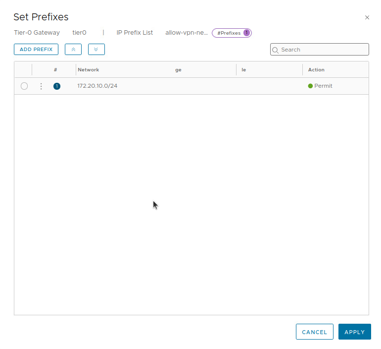
It’s worth mentioning that prefix lists operate with an implied default ‘DENY‘ action; this means that anything that is not explicitly allowed or denied in a prefix list will be automatically denied. In our prefix list above, the first “line” in the list is permitting ‘172.20.10.0/24‘. Any other networks will not match this first entry, and will hit the implied ‘DENY‘ rule.
Now we are returned to the ‘Set IP Prefix List‘ screen, where we click ‘SAVE‘ for our new ‘allow-vpn-network‘ entry, and then click ‘CLOSE‘ at the bottom.

5b. Configure BGP Neighbor
Returning to the T0 configuration screen, we can now configure the VTI on our remote VPN peer as a BGP neighbor. Expand the ‘BGP‘ section in the T0, and click on the number beside ‘BGP Neighbors‘.

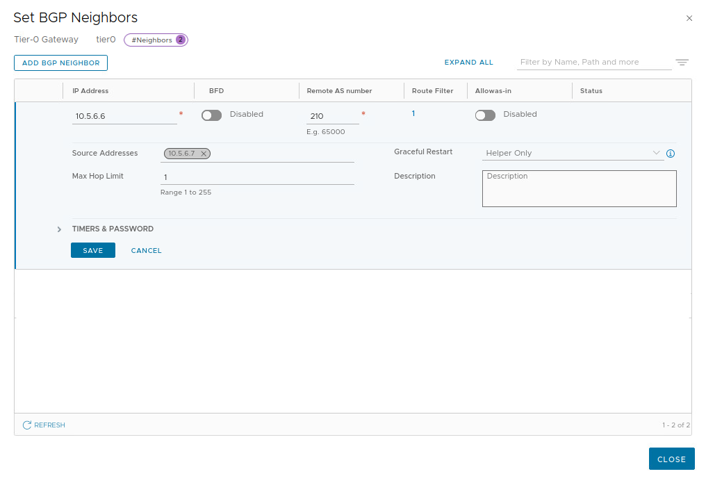
In the ‘Set BGP Neighbors‘ window, click the ‘ADD BGP NEIGHBOR‘ button. For the new BGP neighbor entry, enter the IP address of the remote peer’s VTI (‘10.5.6.6‘) and AS number (‘210‘). Also select the T0 VTI’s IP address from the drop down list (‘10.5.6.7‘) under ‘Source Addresses‘; this ensures that the BGP neighbor relationship will only originate from the T0’s VTI.

With this data populated, click the ‘Set‘ link under the ‘Route Filter‘ column. In the ‘Set Route Filter‘ window, click the ‘ADD ROUTE FILTER‘ button to create a new route filter. As we will be utilizing our previously created IP prefix list to filter our advertised routes, click ‘Configure‘ under the ‘Out Filter‘ column.

In the ‘Select Out Route Filter‘ window, click the radio button beside the target IP filter list (ours is ‘allow-vpn-network‘), and click the ‘SAVE‘ button at the bottom.

We are returned to the ‘Set Route Filter‘ window, you will now see a number listed in the ‘Out Filter‘ column. Click the ‘ADD‘ button to add our new route filter, and then click ‘APPLY‘ at the bottom (‘APPLY‘ in the below screen is greyed out as we have not yet hit the ‘ADD‘ button.)

Now we are returned to the ‘Set BGP Neighbors‘ screen.
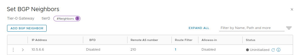
Click ‘Save‘ and then ‘Close‘. After a few moments, the ‘Status‘ column will move from ‘Uninitialized‘ to ‘Success‘, as shown below:

From the ‘Set BGP Neighbors‘ window, we can also click the 3 dots beside a given neighbor and select ‘Download Advertised Routes‘ or ‘Download Learned Routes‘ to get a CSV formatted text file that lists the routes we are advertising to our neighbor as well as routes learned from them.
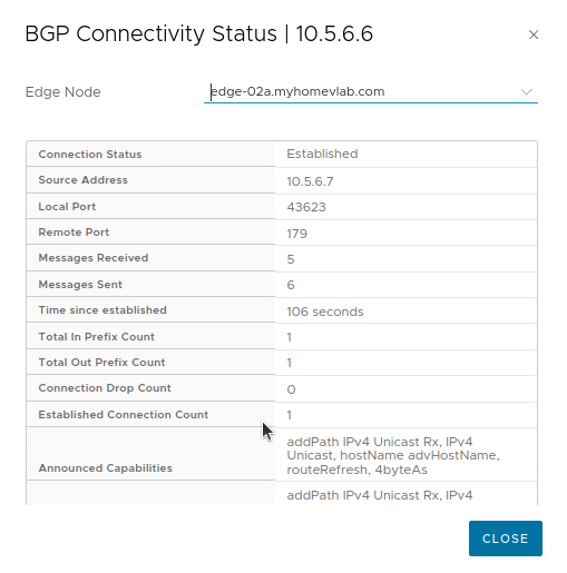
Additional information can be found directly on the T0 SR by connecting to the Edge Node that hosts the active T0 SR. Demonstrated below is a listing of the routes learned from the remote peer:
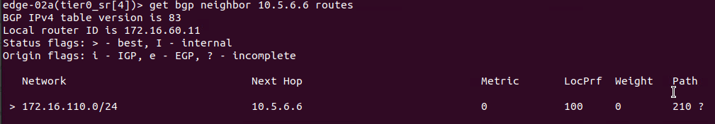
As you can see, only ‘172.16.110.0/24‘ is being learned by our T0 SR, as this is the only network that ‘Router B‘ is advertising. We can also look at the routes being advertised to the remote peer in much the same way:
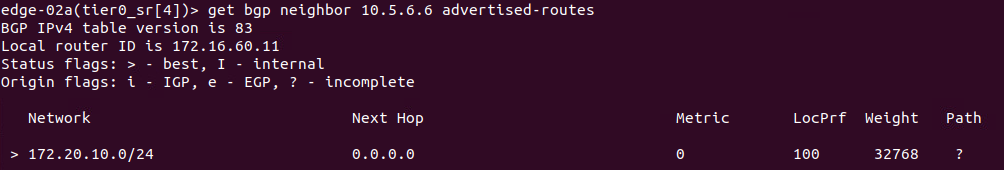
Due to our applied IP prefix list, the T0 SR is only advertising the ‘172.20.10.0/24‘ network to the remote VPN peer.
Wrap Up
Key takeaways for a Route Based VPN in NSX-T utilizing Dynamic Routing:
- A Dynamic Route Based VPN can be terminated on a A/S T0 SR only.
- To configure a Route Based VPN in NSX-T, the recommended order of steps is:
- Create IKE and IPSec profiles (if required)
- Create a VPN Service
- Create a Local Endpoint
- Create a Route Based IPSec Session
- Configure BGP
Thanks for reading!
