In our first post, we provided a L3 VPN scenario and discussed Policy and Route Based VPNs. Following this, we provided a breakdown of our lab environment that we will be using. Today, we will demonstrate how to configure a Policy Based VPN using our scenario.
Policy L3 IPSec VPN scenario

As a scenario refresher, we have two environments (“blue” and “green”) separated by a data center interconnect (DCI). The blue network provides connectivity for a VM via NSX-T and the green network provides connectivity for a bare metal server via a router. While we could easily route between the VM network and Server network, our InfoSec group has a requirement that traffic traversing the DCI must be encrypted.
Configuring an IPSec Policy Based VPN
As discussed in the lab environment breakdown, we will build a Policy based VPN utilizing a T1 SR. Before beginning, ensure the target T1 has been instantiated with an SR; a Distributed Router-only (DR) T1 cannot provide VPN services. Refer back to this diagram for additional information.
Below is the order of operations in the NSX UI (located under Networking -> VPN) we are using to configure a L3 Policy Based VPN in NSX-T:
- Profiles
- IKE Profiles
- IPSec Profiles
- DPD Profiles
- VPN Services
- Local Endpoints
- IPSec Sessions
1. Profiles
When establishing a IPSec tunnel, a two phase process is performed: the IKE Phase (aka Phase 1) and the IPSec phase (aka Phase 2). To prevent mismatches in VPN tunnel negotiation, it’s best to ensure that all of the configuration elements of the selected profiles on each end of the tunnel are identical.
Configuration of VPN profiles is performed under Networking -> VPN -> Profiles. For our purposes today, we will use some of the built-in NSX IKE and IPSec profiles for the L3 IPSec Policy Based VPN.

Above are the IKE profiles built into NSX-T, and we’ve expanded the profile we will be using (‘nsx-default-l3vpn-ike-profile‘). The IKE version is ‘IKE V2‘, using an Encryption Algorithm of ‘AES 128‘ and a Digest Algorithm of ‘SHA2 256‘. We can also see the Diffie-Hellman Group (‘Group 14‘) and the SA Lifetime is set to ‘86400‘.
In our lab, the Vyos router to which we are terminating a VPN tunnel has an IKE profile configured to match the ‘nsx-default-l3vpn-ike-profile‘ settings. However, if the other side of the VPN tunnel needed different settings (say, a vendor that only supports IKE V1), then you would create and configure a custom IKE profile in NSX-T.

We will also use a built-in IPSEC profile (‘nsx-default-l3vpn-tunnel-profile‘), and we’ve ensured it matches the Vyos router’s configuration. Like the IKE profile, if unique IPSec elements are needed to match the peer device, a new IPSec Profile would be created and configured.
There is an additional type of IPSec profile that may be configured, which is a DPD (‘Dead Peer Detection‘) profile. A DPD profile allows us to configure the timers utilized in determining if our IPSec peer is down. We will be using the built-in DPD profile (‘nsx-default-l3vpn-dpd-profile‘) when constructing an IPSec session later in this post.
2. VPN Services
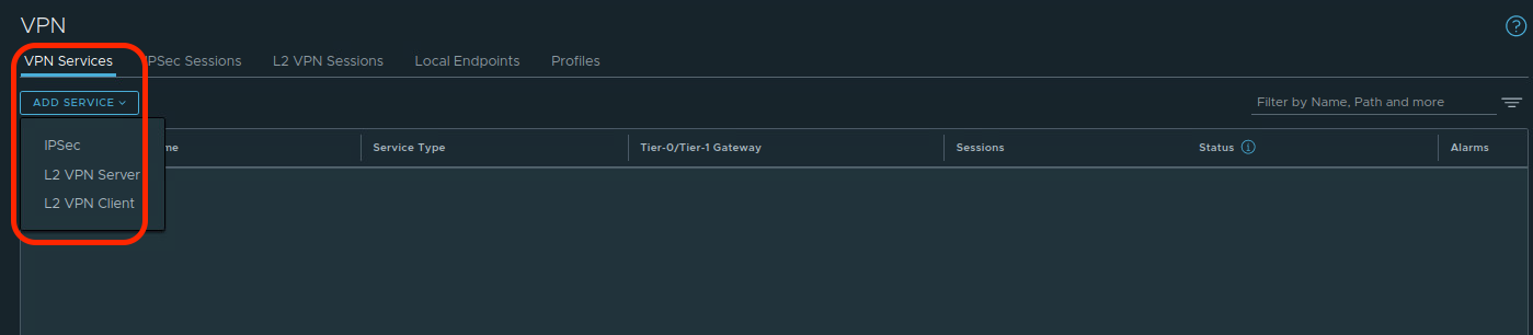
Creating a VPN Service in NSX-T allows us to target a T0 or T1 SR to host an IPSec VPN (which encompasses both Policy and Route based VPNs) or identify it as a member of an L2 VPN (either an L2 VPN Server or an L2 VPN Client). As our focus is IPSec Policy Based VPNs, under the ‘VPN Services‘ heading in Networking -> VPN, click the ‘Add Service‘ button, and choose ‘IPSec‘ from the drop down.
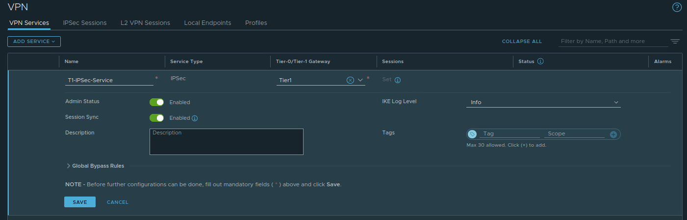
For today’s discussion, all we only need to name the VPN Service (‘T1-IPSec-Service‘) and select the previously deployed T1 SR (named ‘Tier1‘) from a drop down list; all other settings are left to their defaults. You can see our configured VPN Service entry below.
3. Local Endpoints
The IP address to which the remote VPN device establishes a VPN tunnel is known as the ‘local endpoint‘. In the diagram below, the T1 SR has a local endpoint of 172.28.0.1, and Router B is using one of its own interfaces as a local endpoint, which is 172.16.250.4. When we configure an IPSec session later in this post, we will target the Router B’s local endpoint IP as a ‘remote peer‘. Conversely, Router B targets the T1 SR’s local endpoint as a ‘remote peer‘.

Under the ‘Local Endpoints‘ heading in Networking -> VPN, click ‘Add Local Endpoint‘. For today, we only need to add a Name (‘T1-LE‘), select the previously created VPN Service (‘T1-IPSec-Service‘), and enter the IP address that we wish to use (‘172.28.0.1‘). After hitting ‘Save‘, a local endpoint for this VPN service is created.

Now that we have successfully created a local endpoint on our T1 SR, we must ensure the remote peer can reach it. First, configure the T1 SR to advertise IPSec local endpoints via enabling ‘All IPSec Local Endpoints‘ under ‘Route Advertisement‘. This ensures that our T0 is now aware of any T1 SR IPSec local endpoints and how to reach them.

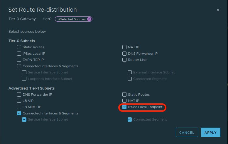
As eBGP is configured between the blue T0 and the blue router, we can advertise the T1 SR local endpoint to Router A, and ultimately on to Router B. In the T0 configuration, open the ‘Route Re-distribution‘ heading, and edit the route re-distribution configuration. Ensure that the ‘IPSec Local Endpoint‘ in the ‘Advertised Tier-1 Subnets‘ section is enabled (see below) and click ‘Apply‘.
Before moving on, let’s take a look a the T1 SR interfaces on the Edge Node where the Active T1 SR resides. On the left below, we can see the T1 SR’s loopback interface before we have created a local endpoint: the loopback interface has an IPv4 address of ‘127.0.0.1/8‘, and an IPv6 address of ‘::1/128‘. After we create the local endpoint, on the right, we can see the loopback interface also has the IPv4 address we associated with the local endpoint (‘172.28.0.1‘).


Right: Post Local Endpoint creation – Click to Enlarge
While the data directly above isn’t necessary for understanding how to build an IPSec VPN, it can be useful to understand “what” happens when a given action (in this case, the creation of a local endpoint) is executed.
4. IPSec Sessions
Our final configuration action is taking the elements from the previous steps and combining them into a IPSec Session. Under ‘IPSec Sessions‘, click the ‘Add IPSec Session‘ and select the ‘Policy Based‘ option.

Below is a new Policy Based IPSec Session, and we’ve circled four areas of interest. While there are additional configurable elements we’ve not highlighted, we’ll be ignoring them as they are not required for today’s scenario.

In the red circle, enter a name for the IPSec Session (‘T1-Policy-Based-VPN‘) and then select the previously created VPN Service (‘T1-IPSec-Service‘) and Local Endpoint (‘T1-LE‘) from drop down lists. After this, populate the ‘Remote IP‘ field with the IP address of the remote device that will be terminating our VPN (‘172.16.250.4‘).
Of note: When creating an IPSec Session, if you fail to first create a Local Endpoint, you can do so in the above screen. To the right of the ‘Local Endpoint‘ field, there are 3 dots; click them and choose ‘Create New‘. However, the same is not true for the ‘VPN Service‘, which must be created prior to creating an IPSec session.
In the purple circle, we have identified two elements; the first is the ‘Authentication Mode‘ and it defaults to ‘PSK‘, which stands for Pre-Shared Key. The ‘Pre-Shared Key’ field below it contains the PSK used for our IPSec VPN tunnel; in our case, the PSK is “secret123“. Remember, the PSK entry must be identical on each side of the tunnel.
In the green circle, we find ‘Local Networks‘ and ‘Remote Networks‘. These fields contain the networks that utilize the VPN tunnel. In our lab, the ‘Local Network‘ in NSX is ‘172.20.10.0/24‘ and the ‘Remote Network‘ is ‘172.16.110.0/24‘. Review the Vyos config for the remote side and you’ll find ‘local‘ and ‘remote‘ prefixes are switched; from the perspective of the Vyos router, ‘172.16.110.0/24‘ is local, and ‘172.20.10.0/24‘ is remote.
Lastly, in the blue circle, under ‘Advanced Properties‘, find the IKE, IPSec, and DPD profiles that the IPSec session will utilize. If we had created unique profiles, this is where we would select them via drop down list. As we are using only default profiles today, no changes are required.
Now that our IPSec Session is configured, we hit ‘Save‘, and the tunnel initiation process will begin. Below is a screenshot of our Policy Based IPSec session immediately after hitting ‘Save‘. At this point, the tunnel status is shown as ‘Uninitialized‘ under the ‘Status‘ column.

Shortly after, the IPSec Session status will read: ‘In Progress‘. At this point, the two VPN devices (the T1 SR and Router B) are in the process of negotiating the VPN tunnel creation.

Finally, our IPSec Session moves from ‘In Progress‘ to ‘Success‘. We’ve created a VPN tunnel! Below, we’ve clicked on the “i” symbol beside ‘Success‘ under the ‘Status‘ column. This allows us to see that not only is our Policy Based VPN up, but the source and destination networks that will use the tunnel.

Wrap Up
Key takeaways for a Policy Based VPN in NSX-T:
- A Policy Based VPN can be terminated on a A/S T0 SR or a T1 SR.
- To configure a Policy Based VPN in NSX-T, the recommended order of steps is:
- Create IKE and IPSec profiles (if required)
- Create a VPN Service
- Create a Local Endpoint
- Create a Policy Based IPSec Session
- IKE and IPSec profile configurations should match on each side of the VPN tunnel. If the NSX provided profiles do not work, you must create new ones.
In our next post, we’ll explore configuring a Route Based VPN. Hope to see you there!
