In our previous post, we showed how you can build a policy based VPN utilizing a T1 SR in NSX-T. Today, we will demonstrate how to utilize a route-based VPN via Static Routing.
Before we begin…
While the lab topology we’ll use today is nearly identical to what was used for our Policy Based VPN post, we did need to make a few changes for today’s Route Based VPN discussion.
During the process of building an L3 VPN in NSX, a Local Endpoint is created. For our Policy Based VPN, this IP address was ‘172.28.0.1‘, and was named ‘T1-LE‘. For our purposes today, we created a new Local Endpoint called ‘route-LE‘ and its IP address is ‘172.29.0.1‘. This local endpoint address is what ‘Router B‘ targets as its VPN peer.
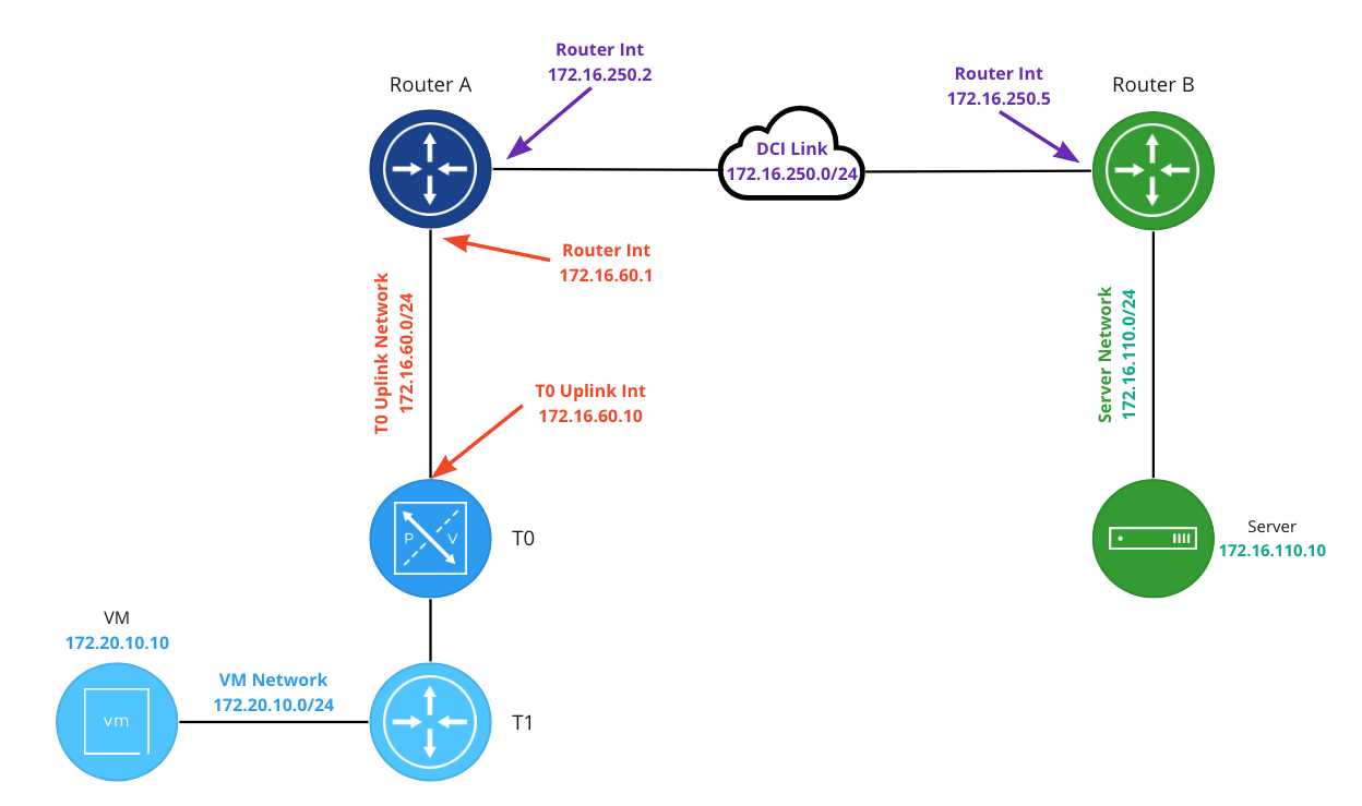
To make switching between a Policy Based and Route Based VPN in our lab easier, a new ‘Router B‘ has been deployed. This new ‘Router B‘ has an interface on the ‘DCI Link‘ of ‘172.16.250.5‘, and has been configured to support a Route Based VPN. The relevant part of the configuration is below:
set interfaces vti vti1 address '10.5.6.6/31'
set protocols static route 172.20.10.0/24 next-hop 10.5.6.7

set vpn ipsec esp-group espgroup1 compression 'disable'
set vpn ipsec esp-group espgroup1 lifetime '1800'
set vpn ipsec esp-group espgroup1 mode 'tunnel'
set vpn ipsec esp-group espgroup1 pfs 'enable'
set vpn ipsec esp-group espgroup1 proposal 1 encryption 'aes128gcm128'
set vpn ipsec esp-group espgroup1 proposal 1 hash 'sha1'
set vpn ipsec ike-group ikegroup1 close-action 'none'
set vpn ipsec ike-group ikegroup1 ikev2-reauth 'no'
set vpn ipsec ike-group ikegroup1 key-exchange 'ikev2'
set vpn ipsec ike-group ikegroup1 lifetime '28800'
set vpn ipsec ike-group ikegroup1 proposal 1 dh-group '14'
set vpn ipsec ike-group ikegroup1 proposal 1 encryption 'aes128'
set vpn ipsec ike-group ikegroup1 proposal 1 hash 'sha256'
set vpn ipsec ipsec-interfaces interface 'eth0'

set vpn ipsec site-to-site peer 172.29.0.1 authentication mode 'pre-shared-secret'
set vpn ipsec site-to-site peer 172.29.0.1 authentication pre-shared-secret 'secret123'
set vpn ipsec site-to-site peer 172.29.0.1 connection-type 'initiate'
set vpn ipsec site-to-site peer 172.29.0.1 default-esp-group 'espgroup1'
set vpn ipsec site-to-site peer 172.29.0.1 ike-group 'ikegroup1'
set vpn ipsec site-to-site peer 172.29.0.1 ikev2-reauth 'inherit'
set vpn ipsec site-to-site peer 172.29.0.1 local-address '172.16.250.5'
set vpn ipsec site-to-site peer 172.29.0.1 vti bind 'vti1'
set vpn ipsec site-to-site peer 172.29.0.1 vti esp-group 'espgroup1'
Configuring an IPSec Route Based VPN
Below are the five steps required for configuring a Route Based VPN on a T1 SR. Steps 1-3 of this process are the same for either a Route Based VPN or a Policy Based VPN. Please refer to the links to this information from our Policy Based VPN post.
- Profiles
- VPN Services
- Local Endpoints – Note: For today, we created a Local Endpoint named ‘route-LE‘ with an IP address of ‘172.29.0.1‘.
- IPSec Sessions
- Create Static Route
After completing the first three steps, we move on to step 4: creating an IPsec Session.
4. IPSec Sessions
In the NSX Manager, under ‘VPN -> IPSec Sessions‘, click the ‘Add IPSec Session‘ and select the ‘Route Based‘ option.

Below is a new Route Based IPSec Session, and we’ve circled four areas of interest. While there are additional configurable elements not highlighted, we’ll be ignoring them as they are not required for today’s scenario.
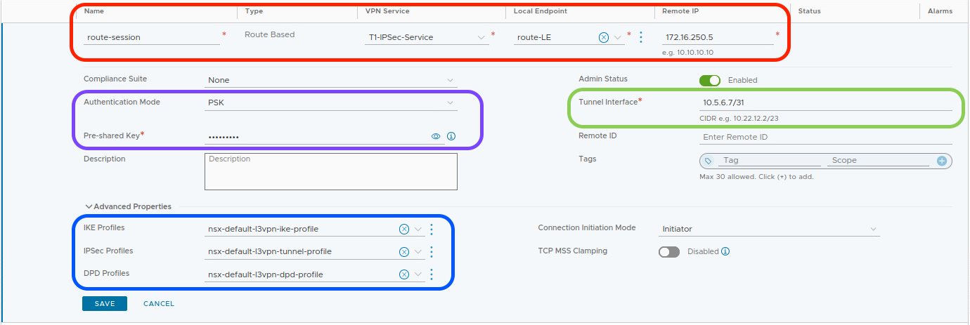
In the red circle, enter a name for the IPSec Session (‘route-session‘) and then select the previously created VPN Service (‘T1-IPSec-Service‘) and Local Endpoint (‘route-LE‘) from drop down lists. After this, populate the ‘Remote IP‘ field with the IP address of the remote device that will be terminating our VPN (‘172.16.250.5‘).
Note: When creating an IPSec Session, if you fail to first create a Local Endpoint, you can do so in the above screen. To the right of the ‘Local Endpoint‘ field, there are 3 dots; click them and choose ‘Create New‘. However, the same is not true for the ‘VPN Service‘, which must be created prior to creating an IPSec session.
In the purple circle, we have identified two elements; the first is the ‘Authentication Mode‘ and it defaults to ‘PSK‘, which stands for Pre-Shared Key. The ‘Pre-Shared Key’ field below it contains the PSK used for our IPSec VPN tunnel; in our case, the PSK is “secret123“. Remember, the PSK entry must be identical on each side of the tunnel.
In the blue circle, under ‘Advanced Properties‘, find the IKE, IPSec, and DPD profiles that the IPSec session will utilize. If we had created unique profiles, this is where we would select them via drop down list. We are using default profiles today, so no changes are required.
Finally, In the green circle, we find ‘Tunnel Interface‘. This fields contains the address (in CIDR notation) assigned to the Virtual Tunnel Interface (VTI). In our lab, we are utilizing ‘10.5.6.7/31‘. As you’ll later see in the ‘Create Static Route‘ step, our T1 SR will utilize the VTI via a static route to send traffic across the VPN.
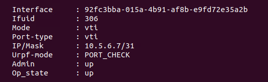
Now that our IPSec Session is configured, hit ‘Save‘. After taking this action, we can observe two things:
- A VTI is created on the T1 SR. Below is a screenshot of the VTI created in our lab:
2. The IPSec session we’ve just created will now enter into a ‘Success‘ status (after briefly being marked as ‘Uninitialized‘ while the tunnel comes up). Below is a screenshot of the new IPSec session:

However, if we click the small “i” symbol beside ‘Success‘ to gather additional data about the tunnel status, we find something that may look unusual to you:
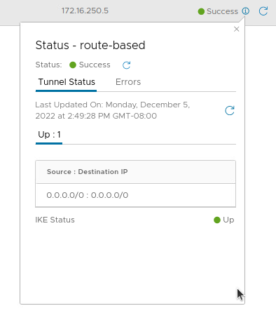
The tunnel shows as ‘Up‘, and both the Source and Destination IP addresses for the tunnel are listed as ‘0.0.0.0/0‘. Back in our Policy Based VPN post, we noted that this information marked the networks ( ‘Local Networks‘ and ‘Remote Networks‘) that are identified by the T1 SR and forwarded across the tunnel.
As its name implies, a Route Based VPN doesn’t evaluate traffic to see if it matches a policy; instead, traffic is routed via the VTI to traverse the VPN tunnel. This is why the IP addresses in the above screenshot are marked as ‘0.0.0.0/0‘; there’s no evaluation of the source and destination IP addresses. As long as a route to a given destination exists in our T1 SR, traffic will be sent over the VPN.
So, with our Route Based IPSec Session successfully configured, we now require a route…
5. Create Static Route
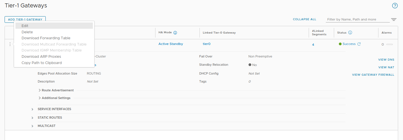
To successfully utilize our Route Based VPN, we need to ensure that traffic to our target destination is routed via our new VTI. As we are terminating the VPN on a T1 SR, we must utilize a static route to forward this traffic (click here for our previous discussion on this topic). To create this static route, in ‘Networking -> Tier-1 Gateways‘, click the 3 dots to the left of our T1 and select ‘Edit‘.
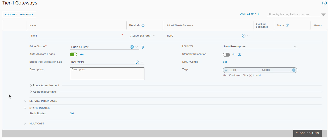
Expand the ‘Static Routes‘ section, and click ‘Set‘ beside ‘Static Routes‘. Note: If your T1 already happens to be configured with static routes, you’ll see a number here instead of the word ‘Set‘. In that case, simply click the number to proceed.
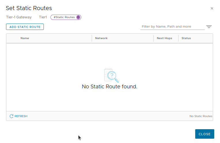
In the ‘Set Static Routes‘ screen. click ‘ADD STATIC ROUTE‘ to create a new static route entry.
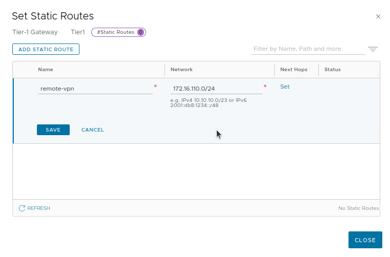
First, we enter a name for our static route (‘remote-vpn‘ below), and the CIDR notation for the destination. In our lab environment, this is ‘172.16.110.0/24‘. Once this data is entered, click the ‘Set‘ link in the ‘Next Hops‘ column.
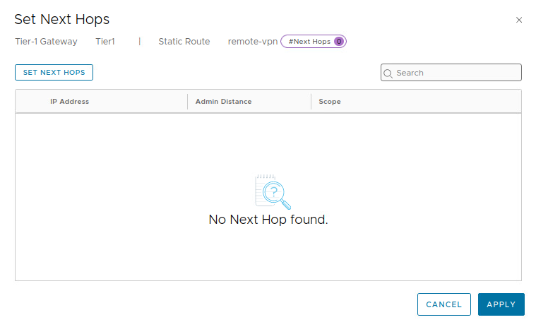
In the ‘Set Next Hops‘ window, click the ‘SET NEXT HOPS‘ button.
For our next hop, we enter ‘10.5.6.6‘, and we can leave the entry under ‘Admin Distance‘ at it’s default of ‘1‘. Click ‘ADD‘, and then ‘APPLY‘.
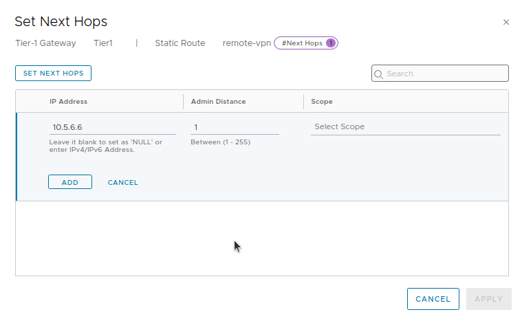
Recall that our VTI is configured with an address of ‘10.5.6.7/31‘. As a /31 subnet allows for 2 total IP addresses, we enter the remaining IP address of the network, ‘10.5.6.6‘, as the next hop.
With this configuration, when traffic destined to ‘172.16.110.0/24‘ reaches our T1 SR, a static route with a next hop of ‘172.5.6.6‘ is utilized. The T1 SR performs a recursive route lookup and finds ‘10.5.6.6‘ is reachable via the VTI’s connected network. By utilizing the VTI, traffic is successfully sent across the VPN tunnel.
Wrap Up
Key takeaways for a Route Based VPN in NSX-T utilizing Static Routing:
- A Route Based VPN can be terminated on a A/S T0 SR or a T1 SR.
- To configure a Route Based VPN in NSX-T, the recommended order is:
- Create IKE and IPSec profiles (if required)
- Create a VPN Service
- Create a Local Endpoint
- Create a Route Based IPSec Session
- Create a Static Route
- IKE and IPSec profile configurations should match on each side of the VPN tunnel. If the NSX provided profiles do not work, you must create new ones.
In our next post, we’ll explore configuring a Route Based VPN utilizing dynamic routing. Hope to see you there!
