As we’ll be reusing the scenario of securing communications between our blue VM and green server throughout the coming posts, we wanted to provide a breakdown of the lab topology that will be utilized. Our intent is to allow you to reference this material as desired via this post, rather than re-populating it over and over in each addition of the series.
Lab Environment for L3 IPSec VPNs
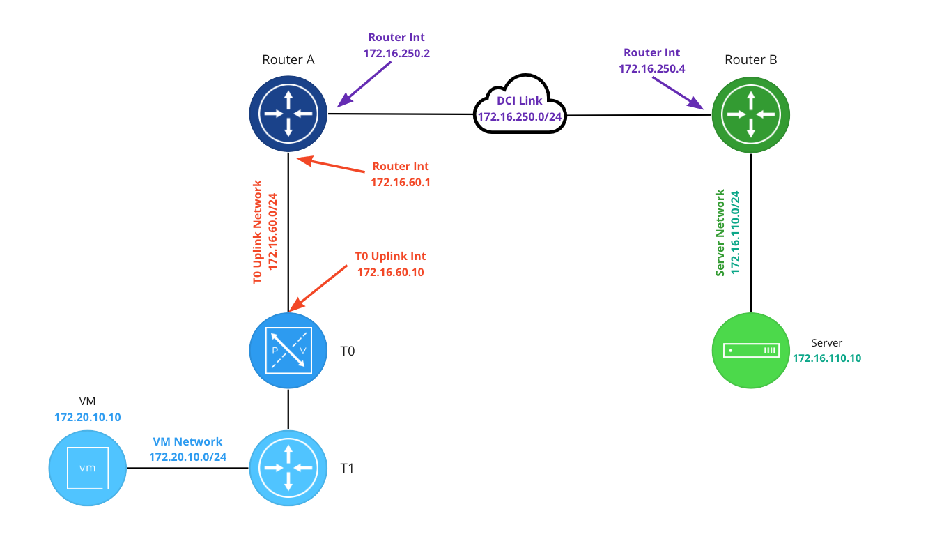
Beginning on the left, the VM network (in blue) is 172.20.10.0/24 and the VM has an IP address of 172.20.10.10. The blue T1 hosts a gateway address for the 172.20.10.0/24 network of 172.20.10.1 (not depicted) and is uplinked to the T0.
In our lab the T0 (in blue) is running in A/S mode. This was a deliberate choice so we could better isolate the connectivity path between all points for exhibition purposes. While an A/S T0 can terminate a L3 IPSec VPN, many of our upcoming posts will demonstrate VPNs terminated on a T1 SR. This will better allow us to show how you may utilize VPNs in NSX-T when an Active/Active T0 is utilized in your environment.
The T0 has a single uplink interface (172.16.60.10) on the ‘T0 Uplink Network‘ which has a network address of 172.16.60.0/24 (in red). The northbound blue router (at the top left) has an interface of 172.16.10.1 connecting it to the ‘T0 Uplink Network‘.
Router A and Router B each have an interface on the DCI Link (172.16.250.0/24): Router A has an interface address of 172.16.250.2, and Router B utilizes 172.16.250.4. Router B is also attached to the ‘Server Network‘ (172.16.110.0/24) via an interface addressed with 172.16.110.1 (not depicted). The server has an IP of 172.16.110.10.
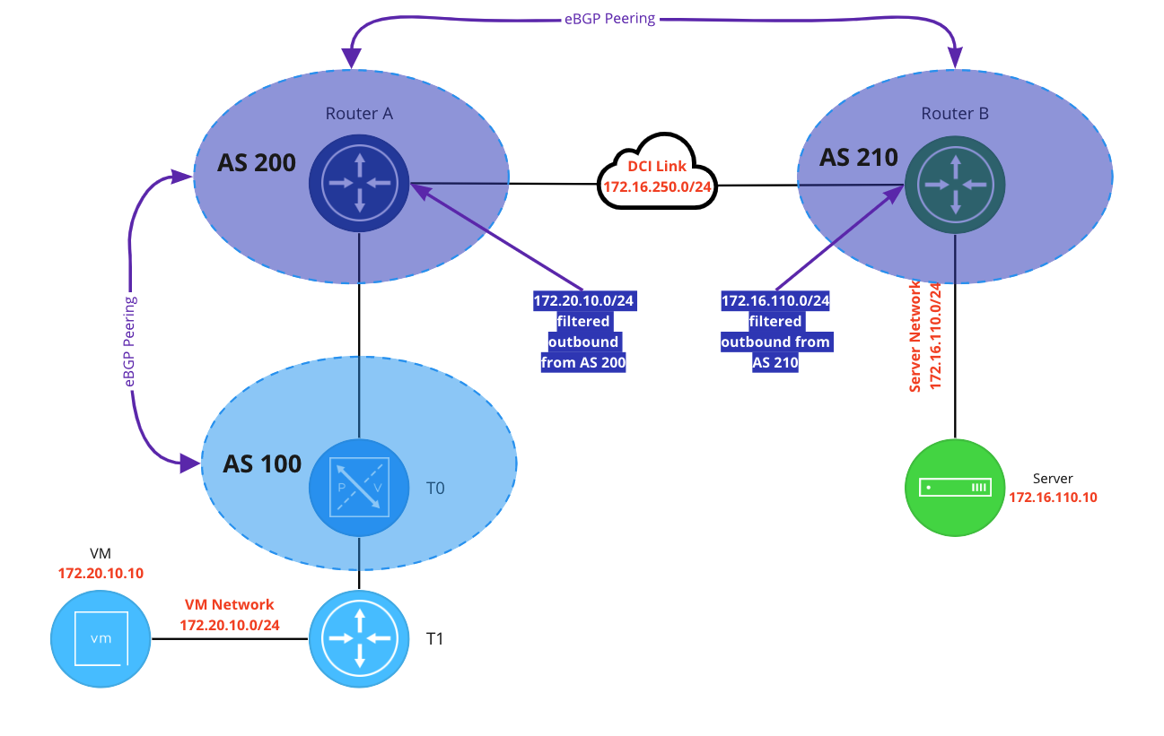
Above is the BGP configuration in the lab. The NSX environment is represented by AS 100, Router A is AS 200, and Router B is AS 210. There’s an eBGP neighbor relationship between the T0 and the Router A, and another one between the Router A and Router B.
For the purposes of the scenario(that traffic traversing the ‘DCI Link’ must be encrypted), we are filtering advertised routes to ensure that traffic between the blue VM and the green server utilizes the VPN. Router A is filtering 172.20.10.0/24 from advertisement outbound, and Router B is doing the same for 172.16.110.0/24. The end result is the Router B does not possess a route to 172.20.10.0/24, and neither Router A nor the T0 have a route to 172.16.110.0/24.
Lastly, below is the VPN configuration of Router B, which is running Vyos 1.3.
set vpn ipsec esp-group espgroup1 compression 'disable'
set vpn ipsec esp-group espgroup1 lifetime '1800'
set vpn ipsec esp-group espgroup1 mode 'tunnel'
set vpn ipsec esp-group espgroup1 pfs 'enable'
set vpn ipsec esp-group espgroup1 proposal 1 encryption 'aes128gcm128'
set vpn ipsec esp-group espgroup1 proposal 1 hash 'sha1'
set vpn ipsec ike-group ikegroup1 close-action 'none'
set vpn ipsec ike-group ikegroup1 ikev2-reauth 'no'
set vpn ipsec ike-group ikegroup1 key-exchange 'ikev2'
set vpn ipsec ike-group ikegroup1 lifetime '28800'
set vpn ipsec ike-group ikegroup1 proposal 1 dh-group '14'
set vpn ipsec ike-group ikegroup1 proposal 1 encryption 'aes128'
set vpn ipsec ike-group ikegroup1 proposal 1 hash 'sha256'
set vpn ipsec ipsec-interfaces interface 'eth0'
set vpn ipsec site-to-site peer 172.28.0.1 authentication mode 'pre-shared-secret'
set vpn ipsec site-to-site peer 172.28.0.1 authentication pre-shared-secret 'secret123'
set vpn ipsec site-to-site peer 172.28.0.1 connection-type 'initiate'
set vpn ipsec site-to-site peer 172.28.0.1 default-esp-group 'espgroup1'
set vpn ipsec site-to-site peer 172.28.0.1 ike-group 'ikegroup1'
set vpn ipsec site-to-site peer 172.28.0.1 ikev2-reauth 'inherit'
set vpn ipsec site-to-site peer 172.28.0.1 local-address '172.16.250.4'
set vpn ipsec site-to-site peer 172.28.0.1 tunnel 0 allow-nat-networks 'disable'
set vpn ipsec site-to-site peer 172.28.0.1 tunnel 0 allow-public-networks 'disable'
set vpn ipsec site-to-site peer 172.28.0.1 tunnel 0 esp-group 'espgroup1'
set vpn ipsec site-to-site peer 172.28.0.1 tunnel 0 local prefix '172.16.110.0/24'
set vpn ipsec site-to-site peer 172.28.0.1 tunnel 0 remote prefix '172.20.10.0/24'
Wrap Up
While this post was relatively short, we hope it is useful in understanding the underlying architecture we are using as we move forward. In our next post, we’ll build a simple IPSec Policy Based VPN. Hope to see you there!
