In broad terms, there are two main types of Virtual Private Networking (VPN) offerings in NSX-T:
- Layer-3 (L3) IPSec VPN
- Layer-2 (L2) VPN
Additionally, there are two subsets of L3 IPSec VPNs:
- Layer-3 (L3) IPSec VPN
- Policy Based
- Route Based
Throughout an upcoming series of posts, we will breakdown both Policy Based and Route Based L3 IPSec VPNs in NSX-T. Let’s begin by looking at a scenario where an L3 IPSec VPN (either Policy or Route Based) could be utilized.
Before we begin…
As of this writing, our lab is using the latest version of NSX (NSX 4.0.0.1). Beginning with this release, the ‘-T‘ from ‘NSX-T‘ is being dropped and the product will simply be referred to as ‘NSX‘ by VMware . However, we did not want readers of this series to believe we were discussing ‘NSX for vSphere‘, so we’ve opted to continue using ‘NSX-T‘ for now.
On to the scenario!
Potential L3 IPSec VPN scenario
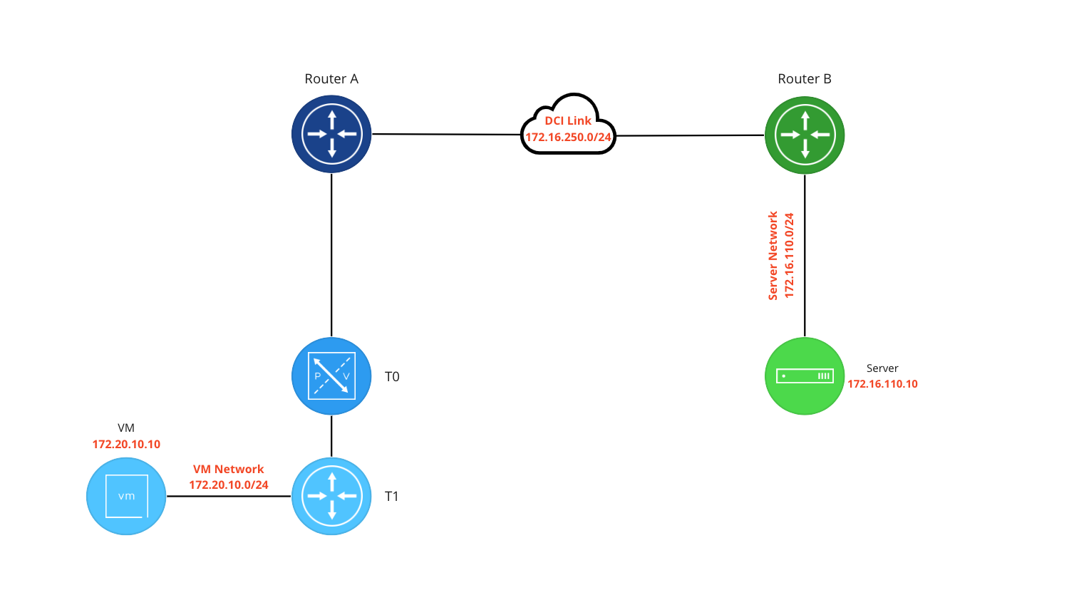
In the above, we have two environments (“blue” and “green”) separated by a data center interconnect (DCI). The blue network provides connectivity to a VM via NSX-T and the green network provides connectivity to a bare metal server via a router. While we could easily route between the VM network and Server network, our InfoSec group has a requirement that traffic traversing the DCI must be encrypted.
To meet this requirement, we’ll create a VPN between the blue NSX environment and the green router. This brings up an important point regarding L3 IPSec VPN in NSX: the peer device for a NSX-T VPN does not have to be in NSX-T. NSX-T can build an L3 IPSec tunnel with any device (router, firewall, etc) that supports the same IPSec configurations.
As an aside, you might look at the above and think “why don’t you just build a VPN between the blue router (Router A) and green router (Router B)?” That is a valid solution, but an advantage of using NSX to construct the VPN is that it moves us closer to an ‘end-to-end‘ encryption model. Rather than having our traffic potentially exposed within the blue environment before it reaches Router A, terminating the VPN tunnel in NSX encrypts the traffic closer to the source (in our case, the blue VM).
Selecting between NSX-T IPSec Policy Based VPN or Route Based VPN
When selecting L3 IPSec VPN with NSX-T, you must choose between a Policy Based VPN or a Route Based VPN. Additionally, we must choose where a L3 IPSec VPN will terminate: either on a Tier-0 (T0) or a Tier-1 (T1) Service Router (SR). The flowchart below will help you understand where (T0 or T1) VPNs can be utilized in NSX-T.

For deployment on a T0, there’s a single point to consider: Is the T0 in Active/Active (A/A) or Active/Standby (A/S)? In order to terminate a VPN of any kind, the T0 must be configured in an A/S mode.
As found on the right of the diagram, we can also terminate a L3 VPN on a T1. The first choice identifies a prerequisite for terminating a VPN on a T1: the T1 must be a T1 SR. This means the T1 has to have an Edge cluster selected as part of its configuration, which results in a T1 SR being instantiated.
The second question in our T1 decision tree regards routing protocols: is dynamic routing via BGP required for our VPN? While we will dive into this in future posts, know that a T1 SR can support Policy based VPNs or Route Based VPNs utilizing static routing. If you have a requirement to support dynamic routing over the tunnel via BGP, then your only option is to terminate on a T0 SR.
L3 IPSec Policy Based vs Route Based VPN in NSX-T
Now that we’ve discussed where L3 IPSec VPNs can be terminated in NSX-T, let’s review each type of L3 IPSec VPN in additional detail.
L3 IPSec Policy Based VPN
With firewalls, a series of rules containing a source, destination, port and protocol (and depending on the vendor, other options) are evaluated as traffic is received or sent on an interface. If traffic matches a rule, the associated action (Allow, Deny, Drop, etc) is taken.
A Policy Based VPN operates in a similar fashion: we identify networks that will utilize the tunnel (‘local networks‘) as well the networks we wish to reach (‘peer networks‘) via the VPN. As traffic is received from by our VPN device, if the traffic matches these configured networks, it is encrypted and sent to the ‘peer‘ VPN device (the VPN device on the other side of our tunnel), where it is decrypted and passed on to the destination.
Policy Based VPNs require explicit identification of the networks that will be using the tunnel, often referred to as a “static” VPNs. If you have an existing Policy Based VPN, and you wish to allow a new network to utilize it, the configurations on each side of the tunnel must be altered to allow the new network.
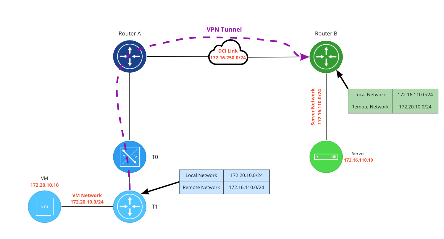
Above is a Policy Based VPN configured on a T1: the ‘local network‘ is defined as 172.20.10.0/24, and the ‘remote network‘ is 172.16.110.0/24. In contrast, Router B’s ‘local network‘ and ‘remote network‘ configurations are flipped: 172.16.110.0/24 is ‘local‘ to the it, while 172.20.10.0/24 is ‘remote‘. When traffic from the VM at 172.20.10.10 attempts to reach our server at 172.16.110.10, it matches the T1 VPN policy, and is sent via the VPN tunnel to Router B, where it is decrypted and delivered to the server.
In this same scenario, if the VM sends traffic to a destination that is not identified as a ‘remote network‘, it will not match the configured VPN policy on the T1 SR, and will not be encrypted.
NSX-T L3 IPSec Route Based VPN
Whereas Policy Based VPNs are considered “static”, Route Based VPNs are “dynamic”. The requirement for Policy Based VPNs to explicitly configure each side with the networks traversing the tunnel does not apply to Route Based VPNs. Instead, traffic routed via a Virtual Tunnel Interface (VTI) on the local VPN device is encrypted and sent to the peer VPN device.
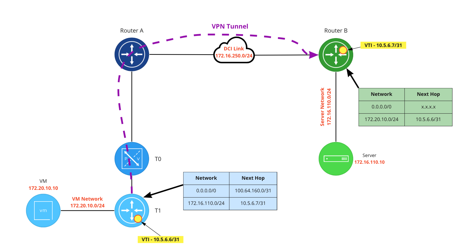
When the VM at 172.20.10.10 communicates with 172.16.110.10, the traffic is first received by a T1 DR (not depicted) and then routed to the T1 SR. Unlike a Policy Based VPN, this traffic is not evaluated for a source/destination match; instead, the blue T1 SR has a static route for 172.16.100.0/24 with a next hop of the green router’s VTI address (10.5.6.7/31). As the blue T1’s VTI is on this same subnet (10.5.6.6/31, depicted in yellow on the blue T1), it is utilized to reach the next hop. The result of this routing action via the VTI is the traffic is encrypted and sent to the peer VPN device (Router B).
Route based VPNs on NSX-T may also utilize dynamic routing via BGP. This allows for scenarios such as having a tunnel to a “primary” and a “secondary” site, with the “secondary” being utilized in the event that the “primary” site is down. We’ll evaluate this functionality in future posts, but for now we simply wished to identify it as a feature of Route Based VPNs in NSX-T.
Wrap Up
We covered quite a bit today, but there are a few key points we’d like to emphasize:
- A Layer-3 IPSec VPN (Route based or Policy Based) can terminate on a T0 SR or a T1 SR
- The peer VPN device does not have to be NSX based; any device capable of terminating an IPSec VPN with matching configurations may work with NSX to build a tunnel
- A Policy Based VPN operates in a similar fashion to a firewall – traffic is evaluated for source and destination by the VPN device in order to establish if traffic is encrypted.
- A Route Based VPN encrypts traffic by routing traffic via a VTI. There’s no traffic evaluation as there is in Policy Based; the VPN device simply follows its routing table.
In our next post, we’ll provide detail around the lab environment that we will be using throughout our series. See you then!
