Prior to NSX-T 2.5, Edge Nodes required three distinct N-VDSes to provide both overlay and VLAN connectivity for North/South routing (presuming you have two distinct peering VLANs.) This was largely due to two factors: 1) pre-2.5, Edge Nodes could only host a single TEP and, more importantly 2) the N-VDS could only posses a single teaming profile.
As you’ll see below, without multiple teaming profiles, the only way for a VLAN segment to be pinned to a specific Edge interface was by utilizing a discrete N-VDS. This is how the three N-VDS model originated.
Three N-VDS Edge Node Architecture
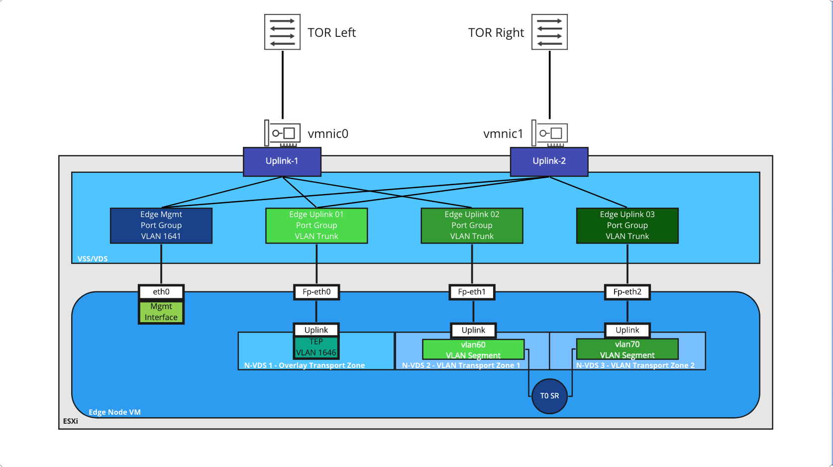
Above, we see an Edge Node VM that resides on an ESXi host; the Edge Node VM has four interfaces (‘eth0‘ for out of band management, and 3 data path interfaces: ‘fp-eth0‘, ‘fp-eth1‘, and ‘fp-eth2‘). Each of the ‘fp-ethX‘ interfaces are bound to a discrete N-VDS, and, in turn, each is attached to a unique port group on the ESXi host’s VSS/VDS.
As VLAN 60 and VLAN 70 are used for deterministic routing (meaning, VLAN 60 only exists on ‘TOR Left‘ and VLAN 70 on ‘TOR Right‘), each VLAN segment that the Tier-0 Service Router (T0 SR) utilizes is placed in a discrete VLAN Transport Zone, which in turn is associated with a specific N-VDS, and each N-VDS is associated with a specific ‘fp-ethX‘ interface. This ‘fp-ethX‘ interface is attached to a specific VSS/VDS port group which is configured to use only one of the available physical NICs on the ESXi host.
For example, the ‘vlan60‘ segment is a member of the ‘VLAN Transport Zone 1‘ transport zone. This transport zone is attached to ‘N-VDS 2‘ which is assigned ‘fp-eth1‘ interface on the Edge Node. With this configuration, traffic from the T0 SR uplink interface can only egress the Edge Node on ‘fp-eth1‘, which is connected to the ‘Edge Uplink 02‘ port group. Finally, this port group is only attached to ‘vmnic0‘, which is physically cabled to ‘TOR Left‘ where VLAN 60 resides.
Single N-VDS Edge Node Architecture
As of NSX-T 2.5, both VLAN pinning (via ‘Named Teaming Profiles‘) and multiple TEPs (MTEPs) are supported for Edge Nodes. With these capabilities, a single N-VDS can now accomplish what previously required three N-VDSes. As such, most deployments of NSX-T since 2.5 utilize the single N-VDS model.
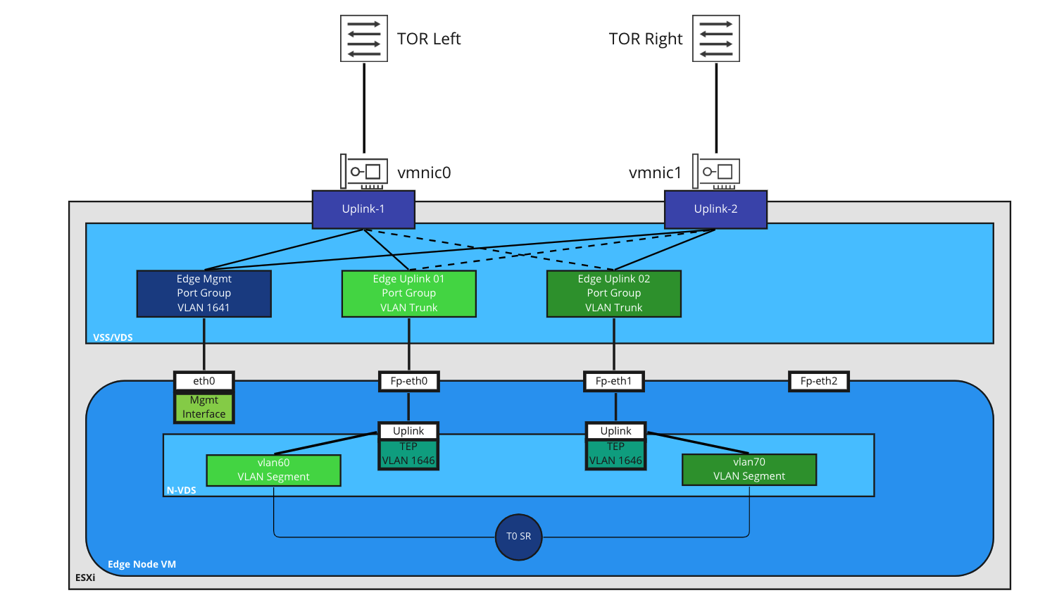
The single N-VDS creates multiple TEPs (one for each uplink defined in the uplink profile). VLAN segments utilized by the T0 SR are pinned to one of the two uplinks: ‘fp-eth0‘ and ‘fp-eth1‘. VLAN pinning allows traffic to be steered to a specific VSS/VDS port group.
As seen in the drawing, the ‘Edge Uplink 01‘ port group is active on ‘vmnic0‘ and standby on ‘vmnic1‘, and the ‘Edge Uplink 02‘ port group is configured in the opposite manner. In this example, traffic on the ‘vlan60‘ segment egresses the Edge Node via ‘fp-eth0‘ to the ‘Edge Uplink 01‘ port group. As ‘Edge Uplink 01‘ is configured for ‘vmnic0‘ as active, this traffic will reach ‘TOR Left‘ to be switched/routed. Conversely, VLAN 70 (via the ‘vlan70‘ VLAN segment) utilizes ‘vmnic1‘, which will reach ‘TOR Right‘.
The three N-VDS model, as of this writing, is still fully supported and works without issue. However, as consumers upgrade their NSX-T environments, there’s often a desire to move to the single N-VDS model that is referenced in all modern VMware documentation. In today’s post, we will break down how one would move from the three N-VDS model to a single N-VDS.
Moving from three N-VDSes to a single N-VDS
In this post, we discuss how to migrate from a three N-VDS model to a single N-VDS on an Active/Standby(A/S) T0 deployment while working to minimize any impact to the environment during the change. We will also be addressing the situation in which a Tier-1(T1) SR (which operates in an A/S model only) is deployed to the same Edge Nodes hosting the A/S T0 SR.
If you’re utilizing an Active/Active (A/A) T0 deployment, the steps are broadly the same, but as all of the T0 SRs are participating in the data path, the idea presented below of upgrading the “standby” T0 SR is not a possibility. We’ll talk a bit more about this toward the end of the post.
If you’d like specifics on the functional differences between an A/S and an A/A T0 deployment, you can view the VMware NSX-T Reference Design Guide here; section 4.6 – Services High Availability.
Before we get started, here are a few points to review:
- The below data was generated in a NSX-T 3.1.3 environment. That said, all aspects of what we discuss should work in any NSX-T environment that is at least 2.5.
- You may have noticed all of the examples are for Edge Node VMs attached to a VSS/VDS. If your Edge Nodes are on an ESXi host that has it’s own N-VDS, then replace the below instructions for creating new VLAN trunk port groups with new VLAN trunk segments on the host’s N-VDS.
- The Preparation and Change Window sections attempt to allow one to do as much pre-work as possible before moving into the actual change window. If desired, you could do everything within a single change window.
- The steps may appear redundant in some cases, such as creating new VLAN transport zones rather than attempting to re-utilize existing ones. While you could re-utilize some existing objects, the below steps are deliberately formulated to reduce the complexity of the move. As such, where possible, we’ve elected to create entirely new objects to make everything as clear as possible.
- We always recommend working within an official change window. While every effort has been made to remove any data flow impact, it’s always far safer to presume you may have an outage than to assume that everything will work smoothly with no issues.
Example Topology
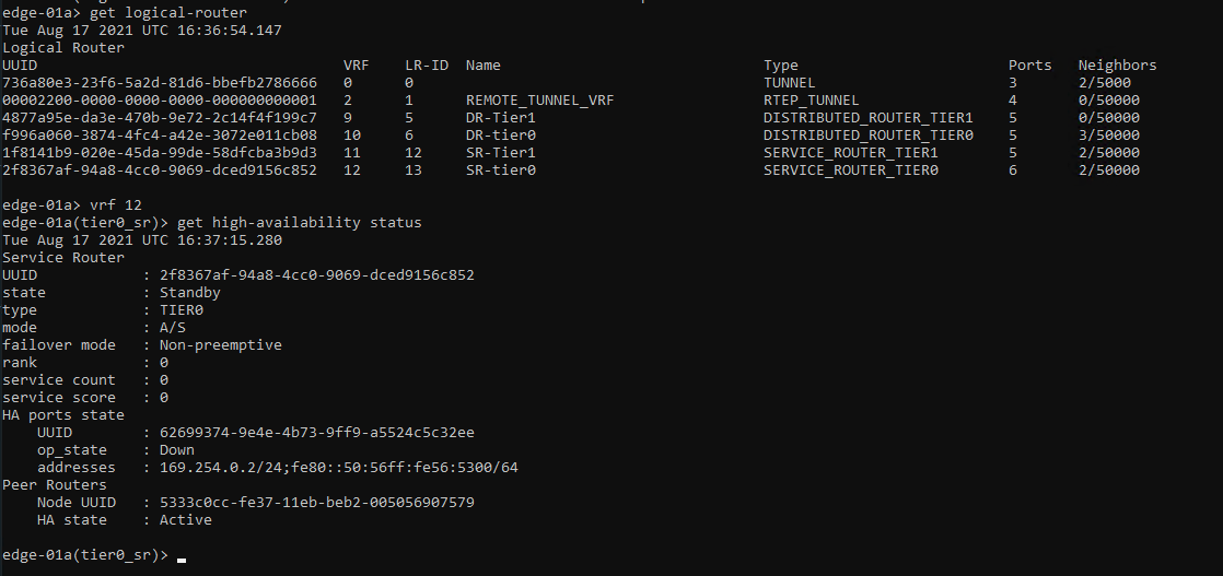
In our example, we have an Edge Cluster that is comprised of two Edge Nodes. An A/S T0 has been deployed to this cluster, as well as a T1 SR. This means that the two Edge Nodes in our deployment will each have a T0 SR, a T0 DR, a T1 SR, and a T1 DR; you can view the list of SR/DRs on an edge from the Edge CLI by executing ‘get logical-routers‘.

Above is a high level breakdown of the T0 SR physical switching configuration. Each T0 SR (both the Active and the Standby) have an uplink interface configured on VLANs 60 and 70. We have BGP configured between the T0 SRs and the physical switches (TORs); however, this same topology could be applicable utilizing static routing (which would require the additional configuration of an HA VIP for the T0).
Remember, while the standby T0 SR is not in the data-path, it still possesses it’s own unique uplink VLAN interfaces and is also peering via BGP with the TORs; the standby advertises the same NSX networks as the active SR, but the path is less preferred due to an automatic AS-prepend of the NSX AS.
Preparation
To prepare for the upcoming migration, the actions below may be performed at any time without potential impact to the environment. The first three steps should be performed in the below order; the final step (‘Create new VSS/VDS Port Groups‘) may be performed at any time.
The recommended order is:
- Create the new single N-VDS uplink profile
- Create a new VLAN Transport Zone
- Create new VLAN segments
- Create new VSS/VDS Port Groups
Step 1: Create the new single N-VDS uplink profile
To utilize a new single N-VDS, we will create a new uplink profile, which is created in ‘System -> Fabric -> Profiles -> Uplink Profiles‘ in the NSX manager.
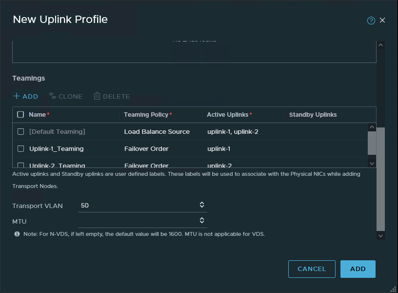
The new uplink profile should be comprised of the following:
- A ‘Default Teaming‘ profile using ‘Load Balance Source‘ with two ‘Active‘ uplinks (here, ‘uplink-1‘ and ‘uplink-2‘). This setting configures multiple TEPs.
- Two additional named teaming profiles, each named for one of the uplinks. Each should be configured for a ‘Teaming Policy’ of ‘Failover Order‘, and only one uplink set as active (here, ‘Uplink-1_Teaming‘ and ‘Uplink-2_Teaming‘, each with a differing ‘Active Uplink’. )
- Enter the same VLAN ID that is set in the current uplink profile utilized by the Edge Nodes for overlay connectivity. Also optionally, set the MTU if it differs from the default.
- Note: The two named teaming profile names will be entered into the new VLAN Transport Zone in the next step. As such, we recommend utilizing uniquely recognizable names that do not conflict with any other named teaming profiles that might be in use elsewhere.
Step 2. Create a new VLAN Transport Zone
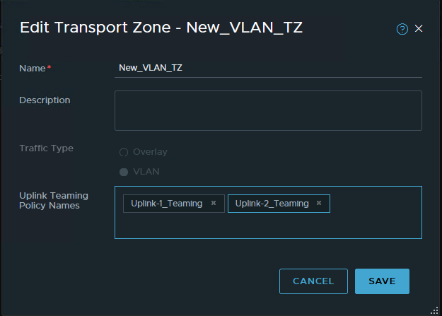
A new VLAN Transport zone will be required, and is created in ‘System -> Fabric -> Transport Zones’. This new Transport Zone should be created with the following:
- Ensure the ‘Traffic Type‘ is configured for ‘VLAN‘
- Enter the two named teaming profiles created in the previous step in the ‘Uplink Teaming Policy Names’ section.
Step 3. Create new VLAN segments
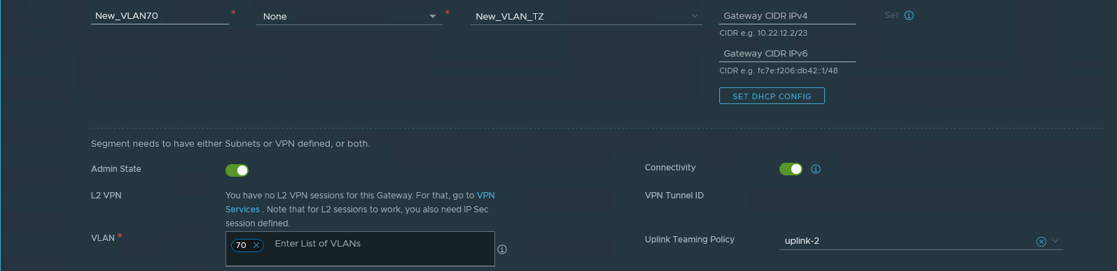
The single N-VDS model utilizes only one VLAN Transport Zone, as VLAN segments can now be pinned to a given uplink. While we are not changing the VLANs that are in use (VLANs 60 and 70 in our example), the existing VLAN segments belong to one of the two original VLAN transport zones. Due to this, we must create new VLAN segments that are members of the new VLAN Transport Zone. In our environment, the T0 SRs have interfaces on two VLAN segments: One on VLAN 60 and another on VLAN 70, so we will need two new VLAN segments.
The new VLAN segments must be created using the following:
- The new VLAN segment names should be easily discernible from the existing VLAN segments.
- Utilize the newly created VLAN Transport Zone.
- The VLAN ID must match the VLAN ID of the existing segment that we will be replacing.
- Make sure to select the appropriate ‘Uplink Teaming Policy‘ which pins the VLAN to the desired uplink.
Step 4. Create New VSS/VDS Port Groups
To bring the new single N-VDS within VMware’s recommended architecture, you will create two new VLAN port groups on the ESXi hosts where the Edge Nodes reside. These port groups should adhere to the following recommendations:
- A unique naming convention to make them easily identifiable
- Each port group should be configured for VLAN trunking; you may elect to narrow the scope to desired VLAN IDs only, or you can utilize ‘0-4094‘ to allow all VLANs.
- The first port group should use one physical NIC as ‘Active’ and the other as ‘Standby’. In the single N-VDS diagram above, ‘vmnic0‘ is “Active” and ‘vmnic1‘ is “Standby” for the ‘Edge Uplink 01‘ port group.
- The second port group should be configured in the opposite manner. In the single N-VDS diagram, ‘Edge Uplink 02‘ has ‘vmnic1‘ as “Active” and ‘vmnic0‘ as “Standby”.
Change Window
Once the preparation above is completed, we are now ready to start moving the Edge Nodes over from three N-VDSes to a single N-VDS. We recommend scheduling a change window for this portion.
The steps for the change window are as follows:
- Disable Fail Over Preemption
- Move T0/T1 Active SRs to the same Edge Node (if applicable)
- Remove VLAN backed uplink interfaces on the Standby T0 SR
- Change Standby Edge Node VM vNIC connections in vSphere / vCenter
- Convert Standby Edge Node to a single N-VDS
- Re-create the uplink interfaces for the T0 SR on the Standby Edge Node
Step 1. Disable Fail Over Preemption

On the T0 and a T1 (presuming a T1 SR exists), if ‘Fail Over‘ is configured for ‘Preemptive‘, the setting should be altered to ‘Non Preemptive‘. We will need this feature configured so later we can ensure which Edge Node possesses the ‘Active’ T0/T1 SR. This will allow us to safely conduct changes on the Standby T0/T1 without affecting datapath traffic.
Step 2. Move T0/T1 Active SRs to the same Edge Node (if applicable)
For our T0 /T1 SRs, we first must establish if the Active instance of each is running on the same Edge Node or not. This can be accomplished by either of the following methods:
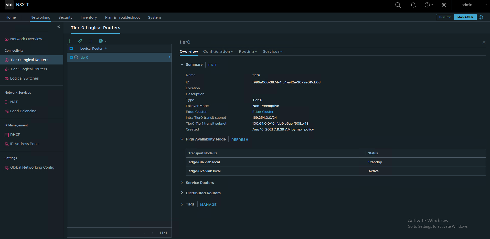
- Via the NSX-T GUI in manager mode (more about manager mode here), click on the T0 and observe which Edge Node possesses the “Active” status under ‘High Availability Mode‘.
- Via console/SSH to an Edge Node and use CLI. Use the ‘get logical-router‘ command to identify the target SR, then execute ‘vrf <#> (VRF number of the target SR)‘. Finally, execute ‘get high-availability status‘ to observe the state of the SR.
If the T0 and T1 Active SRs reside on the same Edge Node, you may proceed to the next step. If not, you will need to perform the following action on one of the Edge Nodes. As the T0 is involved in all aspects of North/South routing, we recommend executing one of the following on the Edge Node that possesses the Active T1 SR:
- Reboot the Edge Node. This can be performed via console/SSH to the Edge Node and issuing the ‘reboot‘ command.

- Place the Edge Node in NSX Maintenance Mode, as depicted above. Within the NSX Manager GUI, go to ‘System -> Nodes -> Edge Transport Nodes‘. Click the check box beside the target Edge Node, then select ‘Actions -> Enter NSX Maintenance Mode‘.
For the latter command, once the Edge Node successfully enters NSX Maintenance Mode, the remaining Edge Node (the one that is not in Maintenance Mode) will now host the Active T0/T1 SR instance. Now select ‘Actions -> Exit NSX Maintenance Mode‘ and allow the Edge Node to return to service. You may choose to verify the target Edge Node no longer hosts any Active SR instances if so desired.
Step 3. Remove VLAN backed uplink interfaces on the Standby T0 SR
Before we can remove the existing VLAN Transport Zones attached to the Standby Edge Node, we first must remove any objects on the Edge Node that are utilizing them. In our example, this means that we must remove the uplink interfaces attached to VLAN segments that are members of the old VLAN Transport Zones.

In Policy view, Go to ‘Networking -> Tier-0 Gateways‘, and Edit the T0 router. Go to ‘Interfaces‘, and click the number that represents the T0 External and Service Interface count.

Note the IP Address/Mask of the Interfaces prior to removing them, as you’ll be re-using this information later.
For each External interface on the Standby Edge Node, click the three dots beside it and select ‘Delete‘. Depending on your existing configuration, you may get an error message saying the Interface can’t be removed because it is in use elsewhere. You will need to remove the configuration element that is causing this action to fail before you can move forward with deleting the interface. Two common causes of this are:
- You are using static routing in conjunction with a T0 HA VIP. If so, remove the IP address from the HA VIP configuration that matches the IP of the External Interface you wish to remove. Don’t remove the entire HA VIP itself; you’ll put the IP back later once you re-add the External Interface.
- You’ve configured BGP Neighbors in the T0 using an explicit ‘Source Address’ entry. The IP address here that matches the IP of the target External Interface must be removed; you can return this entry after re-adding the External Interface.
Step 4. Change “Standby” Edge Node VM vNIC connections in vSphere / vCenter
In vSphere / vCenter, change the connections for the data path interfaces; note that ‘eth0‘ (which will be listed as Network Adapter 1 in vSphere on the Edge Node VM) will remain unchanged. vNIC interfaces ‘fp-eth0‘ and ‘fp-eth1‘ (Network Adapter 2 and 3 in vSphere on the Edge Node VM) should now be attached to the new trunk port groups (‘fp-eth0‘ to one port group, and ‘fp-eth1‘ to the other, as previously discussed) that were created during the Preparation phase. vNIC ‘fp-eth2‘ (Network Adapter 4) may be disconnected as it will no longer be utilized.
Note that as the above changes are implemented, you may see the Edge Node status (in the NSX Manager GUI, go to ‘System -> Nodes -> Edge Transport Nodes‘) as ‘Degraded‘ or ‘Down‘ until the changes below are completed.
Step 5. Convert “Standby” Edge Node to a single N-VDS
The method to convert an Edge Node from a three N-VDS model to a single N-VDS is comprised of several steps. In broad strokes, there are two separate actions: 1) Removing the two N-VDSes that were previously utilized for VLAN traffic and 2) Completing the change to a single N-VDS model.
Step 5-A. Removing N-VDSes on the “Standby” Edge Node

- Go to ‘System -> Fabric -> Nodes -> Edge Transport Nodes‘, select the “Standby” Edge Node checkbox, and click ‘Edit‘ at the top.
- Scroll down to view all three N-VDSes that are installed on the Edge Node.
- Delete each of the N-VDS entries attached to the original VLAN Transport Zones by clicking the ‘DELETE‘ to the right of the N-VDS name. Once both are deleted (leaving a single N-VDS that is still attached to the Overlay Transport Zone), click ‘SAVE‘ at the bottom. This action will free up ‘fp-eth1‘ and ‘fp-eth2‘ interfaces on the Edge Node.
- Note: If you delete the N-VDS entries and continue on without hitting ‘SAVE‘ on the above step, you will receive an error message in the nest step when you hit ‘SAVE‘ informing you that ‘fp-eth1‘ cannot move as it’s in use.
Step 5-B. Completing the change to a single N-VDS on the “Standby” Edge Node
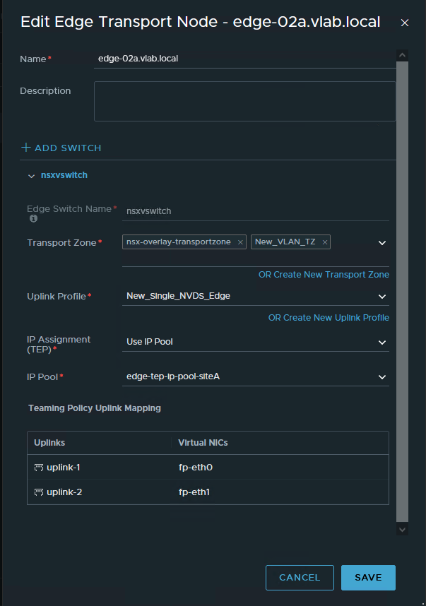
- Back in the ‘Edge Transport Nodes‘ screen, click ‘Edit‘ on the Edge Node again.
- In the existing N-VDS entry, select the new VLAN Transport Zone you created in the ‘Transport Zone‘ drop down. Leave the existing overlay transport zone there. You should now see your overlay transport zone and the new VLAN transport zone listed.
- Click the ‘Uplink Profile‘ drop down and select the new single N-VDS uplink profile you created. You will receive a warning that ‘Virtual NIC mapping has cleared‘. This is expected.
- In ‘IP Assignment (TEP)‘, if you are using an IP Pool , presuming your existing pool has enough free address space, you may leave it as-is. If you are using a static IP list, you’ll need to add another IP as now the Edge Node will have two TEPs, each with a unique IP address.
- Under ‘Teaming Policy Uplink Mapping‘, assign ‘fp-eth0’ and ‘fp-eth1’ to the two uplink entries (‘uplink-1’ and ‘uplink-2’ in the example).
- Hit ‘SAVE‘.
Step 6. Re-create the Uplink Interfaces for the T0 SR on the “Standby” Edge Node
Now that the Standby Edge Node has been converted to a single N-VDS, go to ‘Networking -> Tier-0 Gateways‘, and Edit the T0 router. Go to ‘Interfaces‘, and click the number that represents the T0 External and Service Interface count.
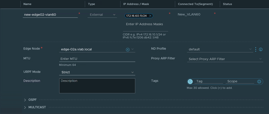
Re-create the External interfaces that were deleted in the Remove VLAN backed uplink interfaces on the Standby T0 SR section above by clicking the ‘Add Interface‘ button .
- A unique name is recommended as to avoid any confusion during the process between old and new uplink interfaces.
- The IP Address/Mask data should match was was previously removed.
- Ensure that you are selecting the new VLAN segments in the ‘Connected To(Segment)‘ that were previously created while configuring these interfaces.
- In the ‘Edge Node‘ drop down, make certain you are choosing the “Standby” Edge Node.
If you select the old VLAN segments, attempting to save will produces an error message, as the Standby Edge Node is no longer a member of the Transport Zones where the old VLAN segments reside.
At this point, if you previously had to edit your BGP Neighbor or HA VIP configuration (as described in the Remove VLAN backed uplink interfaces on the Standby T0 SR section), you may now put those configurations back as they were.
Standby Edge Node configuration complete!!
Once the interfaces are recreated, you will find this Edge Node has successfully returned to service, and is again Standby for T0/T1 SRs. Any BGP sessions should now show as re-established.
As you may have guessed, you will repeat the above process for the Active Edge Node, beginning with your choice to reboot or use NSX Maintenance Mode on the Edge (as detailed above in the Move T0/T1 Active SRs to the same Edge Node (if applicable) section). Once this is executed, the Active T0/T1 instance will reside on the Edge Node that is now on a single N-VDS, and you will be free to move through the steps again.
Once you have fully migrated both Edge Nodes, you may go back and configure ‘Fail Over‘ for ‘Preemption‘ on the T0 or T1 if desired.
But wait… what if it’s an A/A T0 deployment???
Most of what we’ve discussed above is 100% applicable to an A/A T0. In fact, the only real differences should be:
- If the same cluster hosts both the A/A T0 SRs and any T1 SRs, you’ll need to focus on the part of the process around the T1 SR only, as there’s no Standby functionality for a T0 SR in A/A mode. In short, you may want to consider upgrading the Edge Nodes hosting T1 SRs in this situation first (upgrade the T1 SR standby Edge Node, transition it to Active, then upgrade the old Active Edge Node).
- As there’s no Standby T0 SR in an A/A T0, for each Edge Node that is hosting only a T0 SR (no T1 SRs), you can skip the process of using NSX Maintenance Mode or rebooting the Edge Node detailed in Move T0/T1 Active SRs to the same Edge Node (if applicable) section.
During your changes in an A/A environment, as you add back uplink interfaces to the T0 SR on a newly migrated Edge Node, the T0 SR will quickly perform BGP peering and begin in the active data plane routing of traffic.
In the A/S model, BGP peering also happens when the uplink interfaces are back, but the TORs will not utilize the routes being advertised, as the Active is sending a preferred path. This is due to the Standby T0 SR utilizing AS-prepending to make the routes it is advertising less preferable. An example of how this looks from the TOR perspective is below.
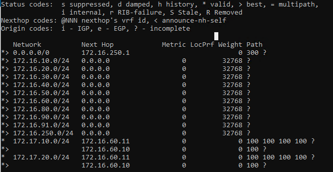
The ‘172.17.10.0/24‘ and ‘172.17.20.0/24‘ networks are each being advertised from ‘172.16.60.10‘ (Active) and ‘172.16.60.11‘ (Standby). For each of these networks, notice that ‘172.16.60.10‘ is advertising a path of ‘100‘, while ‘172.16.60.11‘ has automatically prepended the path with it’s own AS three times, resulting in a path of ‘100 100 100 100‘. Obviously, the TOR in this instance will prefer the shorter path, and utilize the Active T0 SR via ‘172.16.60.10‘.
Until next time….
Hopefully, you found the above useful; admittedly, breaking down the topic turned out to be a more thorough experience than initially thought. However, at a minimum, we hope that the detailed breakdown of the three N-VDS model and how it operates in contrast to a single N-VDS model will be useful for anyone who is responsible for operating NSX-T.
