NSX-T Bridging Use Cases
So far, we’ve covered the mechanics of how bridging works, depicting bridging an overlay segment with physical devices on a VLAN. However, bridging in NSX-T may also be utilized to support your virtual environment. Two common scenarios are 1) migrating VMs from a legacy vSphere environment to a new NSX-T environment and 2) migrating VMs from an NSX-v environment to an NSX-T environment.
Migrating from legacy vSphere environment to new NSX-T environment
There are a number of reasons you might opt to stand up a new NSX-T environment beside your existing vSphere environment (referred to below as ‘side-by-side‘):
- The existing vSphere infrastructure is old, and you will be migrating to new hardware
- A desire to avoid perceived risks associated with installing NSX-T on hosts where workloads currently reside
A common issue with a side-by-side deployment is discovering the VLANs in the legacy environment do not extend past your top-of-rack switches, or perhaps your new NSX-T environment is deployed elsewhere in your data center, with the expectation that any traffic between the two environments will be routed.
If your intention is to re-IP address all of your VMs as you move them into NSX-T, then you will not require a bridging solution; you’ll migrate the VMs and change their IP addresses in the new environment. Unfortunately, changing IP addresses introduces many additional considerations, including updating DNS records, firewall rules, and verifying that workloads continue to properly communicate post-change.
Side-by-side base topology
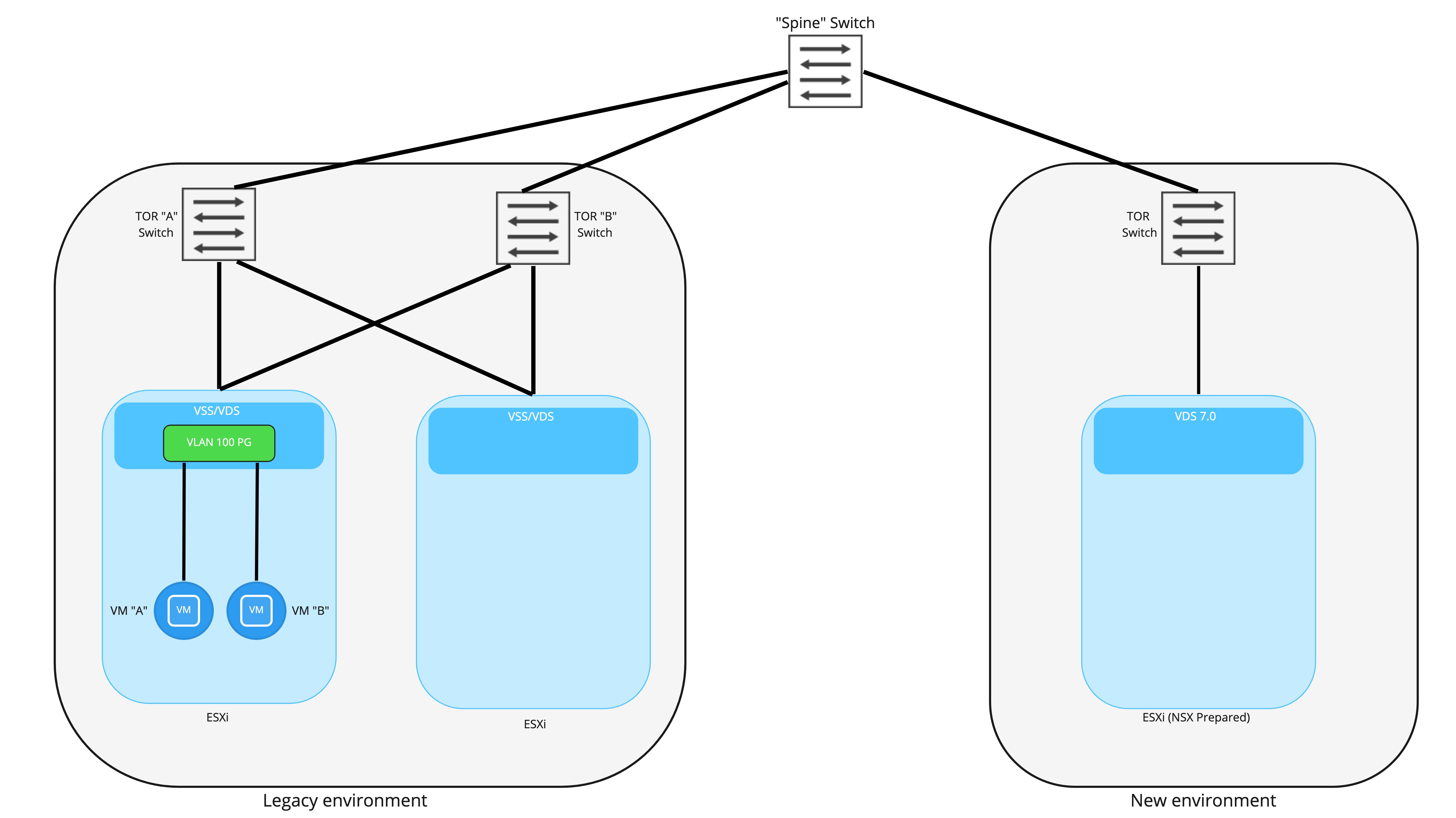
Above is a simplistic look at a side-by-side deployment. On the left, we have our legacy vSphere environment, which is strictly vSphere; all networking is provided by VLAN backed port groups, and routing is performed by the top of rack switches. VM “A” and VM “B” are attached to a port group backed by VLAN 100.
On the right, we have the brand new NSX-T backed environment. These hosts are utilizing vSphere 7.0+ and NSX-T 3.0+, resulting in each host possessing a NSX-T prepared VDS. To keep the diagram from becoming too cluttered, we’ve depicted only a single TOR switch on the new environment; obviously, in a production deployment, two TORs would be utilized for redundancy.
The key takeaway is that each environment is connected to the other via a “spine” switch (for simplicity, only a single spine is depicted), which provides layer 3 connectivity between the two environments. As depicted, all VLANs and their associated IP addressing are isolated to an environment. If we presume that VLAN 100 is associated with 192.168.10.0/24, this network will be isolated to the “Legacy” environment; you could not natively have a VM that resides in the “New” environment attached to this subnet.
Before moving forward, a couple of caveats:
- In some environments TOR switches are purely layer-2 and all layer-3 services are performed by spine switches, effectively allowing all VLANs to exist in both environments if desired. In this case, bridging is not required to move from the “Legacy” environment to “New” environment presuming you are utilizing VLAN logical switches for workloads and not Overlay logical switches (Overlay logical switches require NSX-T to provide routing services).
- If you intend to forklift entire networks one at a time, then bridging would not be required. That is, rather than working in a time period where VMs reside in both the “Legacy” and “New” environments on a given VLAN/subnet, you move all of the VMs in the “Legacy” environment over to the “New” environment in a single window. Unfortunately, some downtime will be experienced as you stop advertising the network from “Legacy” and begin advertising from “New”; until workloads are successfully migrated over to “New”, they’ll have no real network availability.
Bridging Legacy and new sites via NSX Edge
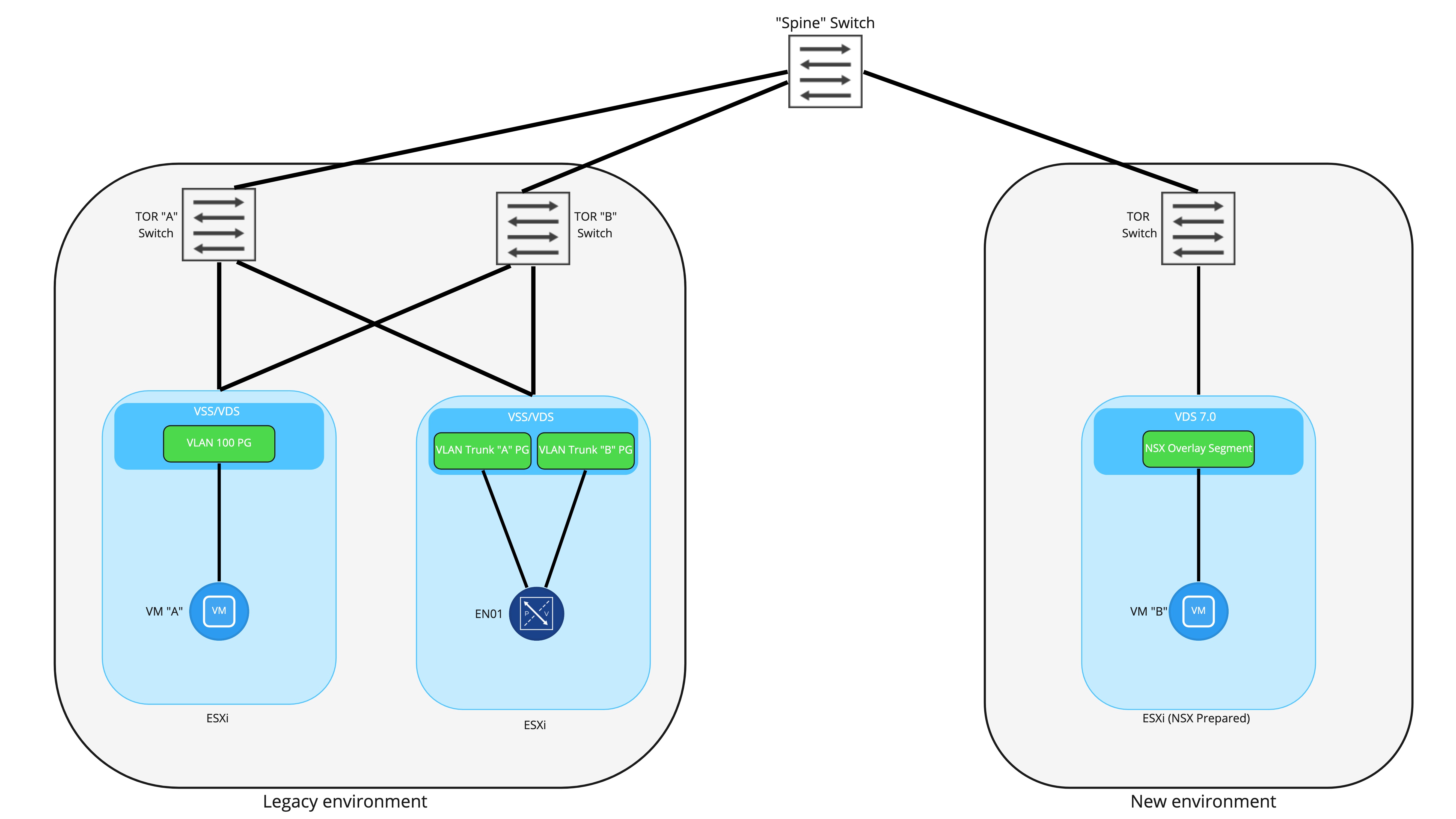
To provide communication between VMs attached to the a VLAN port group and an NSX-T Overlay segment, an NSX-T Edge Node will provide a bridging instance. In the above picture, you can see that the NSX-T Edge Node has been deployed to an ESXi host in the legacy environment and has been connected to two trunk ports. Note: it is not required to ‘NSX prep’ the host in the legacy environment where the Edge will be deployed. It’s also worth mentioning that for production, you should use 2 Edge Node VMs in an Active/Standby model; a single Edge Node VM is depicted here for simplicity.
As detailed in prior posts, this deployment model would utilize 2 N-VDSes in the Edge Node: the first would be for providing overlay connectivity, while the second would be for the VLAN side of the bridge. Note that there would also be a third connection for the management interface of the Edge Node itself, and that would connect to a VLAN backed port group; it’s not depicted above as to keep focus on the bridging itself.
A common question is “Why create two different trunk port groups on the VSS/VDS for the Edge Node to utilize?” You certainly could attach both of the FP-ethX interfaces to a single trunk port group, but by using two, the option of deterministically controlling which physical uplinks provide bridging connectivity is available. This would allow for the VLAN side of the bridge to be “pinned” to one physical uplink, while the Geneve encapsulated side of the bridge can be “pinned” to another.
Deploying the Edge Node VM itself can be accomplished a few ways, but in this scenario, it’s best to simply deploy the Edge Node OVA by hand and then connect it back to the NSX-T manager as described here. Remember that the Edge Node management interface will need a IP address that is valid in the legacy environment, and as long as it reach the NSX-T manager cluster and there are no physical firewalls preventing this access, you will be in good shape.
Back to the diagram itself, you can see that in the new environment, VM “B” has been moved over and is attached to a NSX Overlay Segment. At this point in the diagram, we are presuming that bridging is up and active, VM “A” and “B” will both possess their original IP addressing, and can communicate with each other via the NSX Edge VM.
NSX-T Bridging packet flow
Let’s take a look at exactly how traffic from VM “A” is able to reach VM “B” once the Edge Node VM has been deployed and a bridging instance has been configured. In this case, we’ve configured a segment in NSX-T to be bridged to VLAN 100, which is the VLAN to which VM “A” is connected.
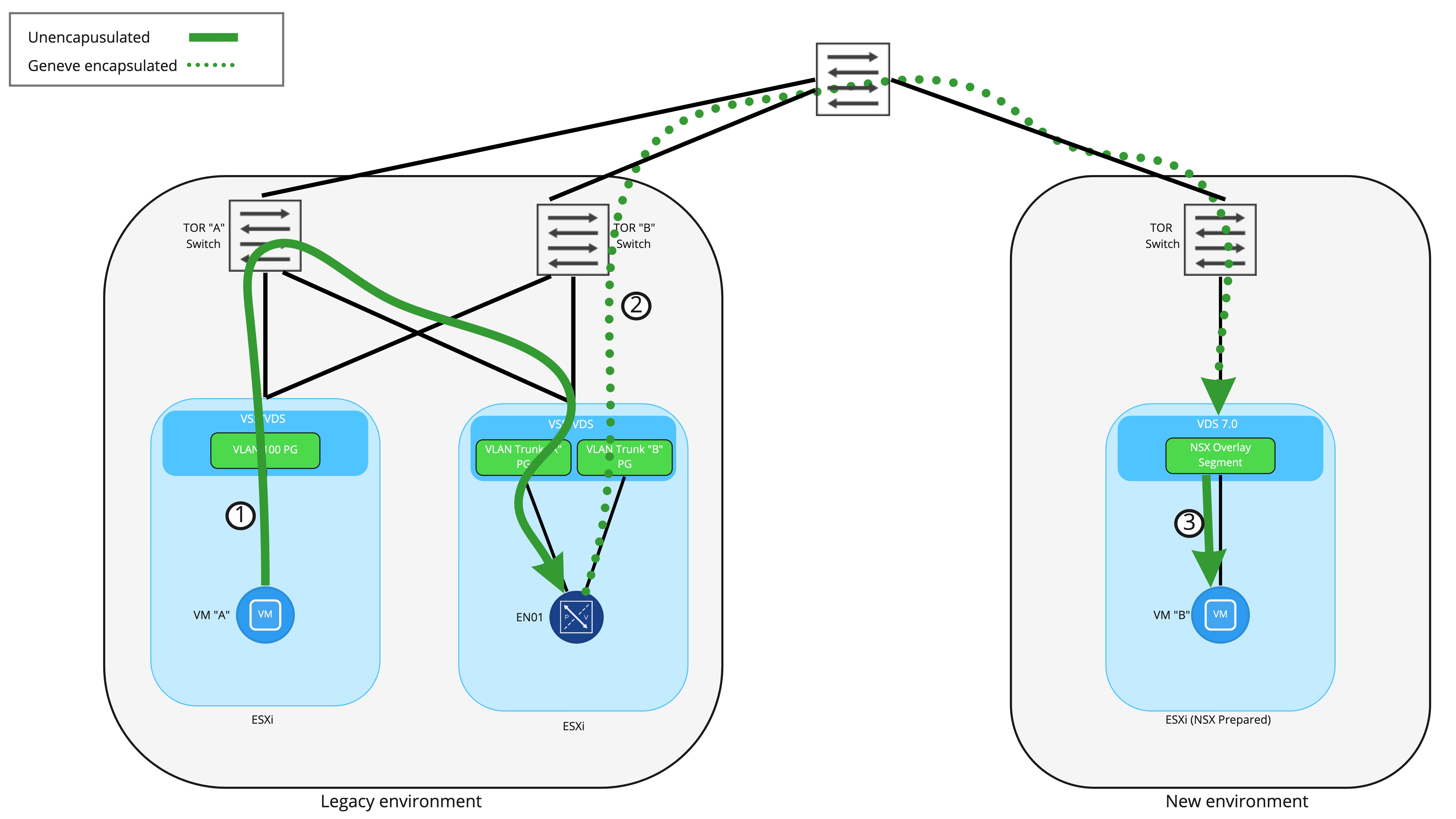
In Step 1, the frame from VM “A” to “B” is first received by the VLAN side of the bridging instance residing on the NSX-T Edge Node VM. This frame has an 802.1q header for VLAN 100 added as the it leaves the ESXi host where VM “A” resides, and is delivered to the Edge Node VM with the 802.1q header still present as the interface on the Edge Node VM is attached to a VLAN trunk port group.
Once received by the bridging instance, the 802.1q header is removed and then the frame is encapsulated inside a Geneve wrapper. As shown in Step 2, the frame is delivered to the target ESXi host where VM “B” resides by routing to the destination TEP . This means that TEP IP addressing (for Edge Nodes and ESXi hosts) must be routable in the network and able to traverse physical firewalls. Finally, Step 3 depicts the ESXi host removing the Geneve encapsulation and delivering the frame to VM “B”.
Conceptually, think of the Edge Node VM performing bridging like any other NSX-T prepared ESXi host. Each has a TEP or TEPs and are responsible for sending and receiving Geneve encapsulated traffic to reach virtual machines. From this perspective, a frame being encapsulated in Geneve via the Edge Node VM and sent to the destination is functionally no different than a NSX-T prepared ESXi host performing the same action.
Key Takeaways
A key takeaway from this discussion is that NSX-T Edge Node VMs possess their own TEPs. This is in stark contrast to the ESG in NSX-v, which was a virtual machine that relied on the ESXi host upon which it resided for overlay encapsulation services. With the TEP on the Edge Node VM itself, it may reside on any ESXi host you wish, regardless if that ESXi host has no NSX at all, or is NSX-T prepared… or even NSX-v (more on this later).
One note about using an Edge Node VM for bridging in the above on vSphere – Since we are attaching the Edge Node VM to VLAN trunk port groups, this means that the Edge itself can bridge many logical segments to many VLANs. For instance, above we only depict VLAN 100 being bridged to an overlay logical switch. However, this same edge node can also bridge additional logical switches to VLAN IDs.
For an explicit example, let’s say VLAN 100 is already bridged to an overlay segment called ‘Web Segment’ via a pair (remember, Active/Standby model is recommended) of Edge Node VMs. These exact same Edge Node VMs could also bridge:
- ‘App Segment’ to VLAN 200
- ‘DB segment’ to VLAN 300
- ‘Test segment’ to VLAN 400
In fact, as of NSX-T 3.1.2, a single Edge node can bridge 512 pairs of VLANs to overlay segments!
The reason this is being mentioned so specifically is 1) people often forget that an Edge Node VM can bridge more than a single pair of VLAN to overlay segments and 2) things are a bit different when we discuss our next topic, “migrating VMs from a NSX-v environment to a NSX-T environment. “
See you in our next post!
