Picking up where we left off in Part One, let’s take a look at our second question: How do I configure the VLAN side of the bridge? As a refresher, these are the two options for Edge VM placement we identified last time:
- Any vSphere host using a VSS/VDS, including vSphere 7.0+ host that are NSX-T 3.0+ prepped
- An NSX-T 2.4+ prepared host that is utilizing the N-VDS
How do I configure the VLAN side of the bridge?
When using the Edge Node VM for bridging, the VLAN side of the bridge requires explicit configuration to make everything work. As previously mentioned, this VLAN connectivity will be provided by either a VSS/VDS port group or an NSX-T VLAN segment.
Let’s start by looking at how a VSS/VDS works in comparison to a physical switch and why these configurations are required.
Physical switching basics
Many years ago there were regular discussions around “hubs vs switches” as switches were becoming more common. At it’s most basic, a layer 2 (L2) frame received by a hub gets repeated to all ports indiscriminately. This means every device connected to a hub receives a copy of all frames, regardless if the traffic is actually destined for that device.
By comparison, an advantage of a switch is that it learns the MAC address of every device attached by observing the source MAC address of an L2 frame. This means that a frame for a destination is sent only to the port where the destination MAC resides. The only time a frame is repeated to all members of a switch is when it’s is deliberately intended to do so, such as a broadcast frame.
VLANs on a switch allow us to narrow the L2 broadcast domain further, ensuring that a L2 broadcast frame on a VLAN is only repeated to other member ports of that same VLAN, and not all ports on a switch.
Physical Switch vs Virtual Distributed Switch
So now that we’ve discussed how a physical switch handles L2 frames, let’s look at how a VSS/VDS operates by default. To begin, a physical switch can be separated logically via VLAN constructs, a VSS/VDS is logically separated by port groups. A port group is typically assigned to a VLAN and each VM that is attached to this port group is a member of said VLAN.
Whereas a physical switch will learn the MAC addresses on a port by observing the frames traversing it, the VSS/VDS only knows the MAC addresses of the virtual machines that are attached to it. That is, the VSS/VDS is not observing and then learning the MAC addresses like a physical switch; it’s simply programmed with the MAC address of a VM once it’s attached to a port group.
Let’s look back at the logical diagram that was presented in Part One.
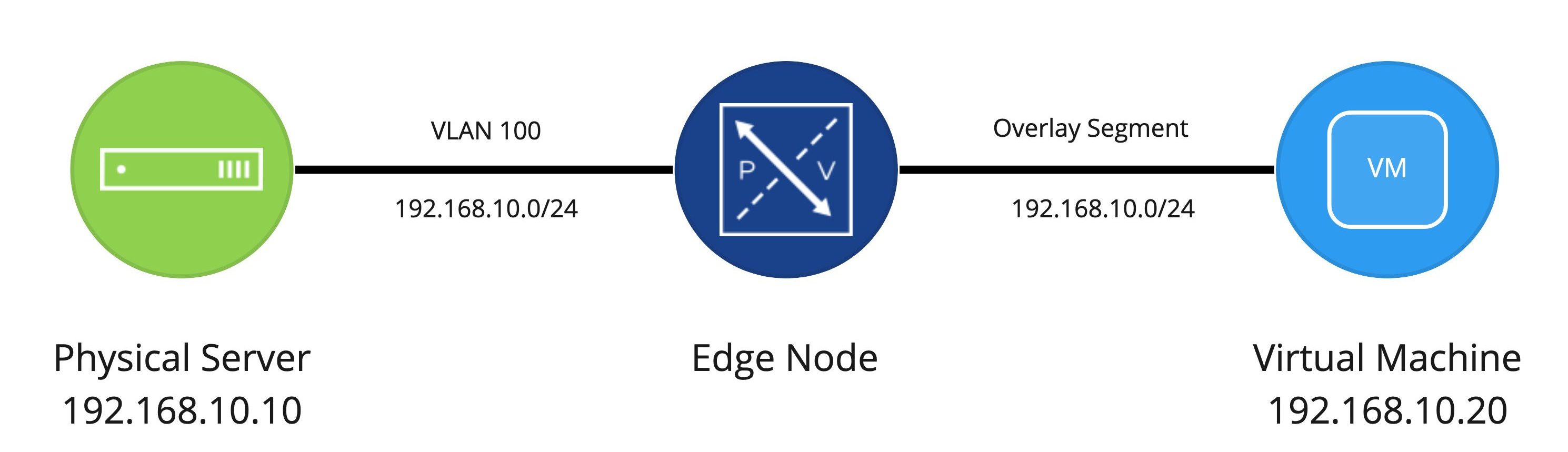
Now, using this logical diagram as a base (one physical server, one Edge Node VM, and one virtual machine), let’s focus on the physical and virtual switching components.
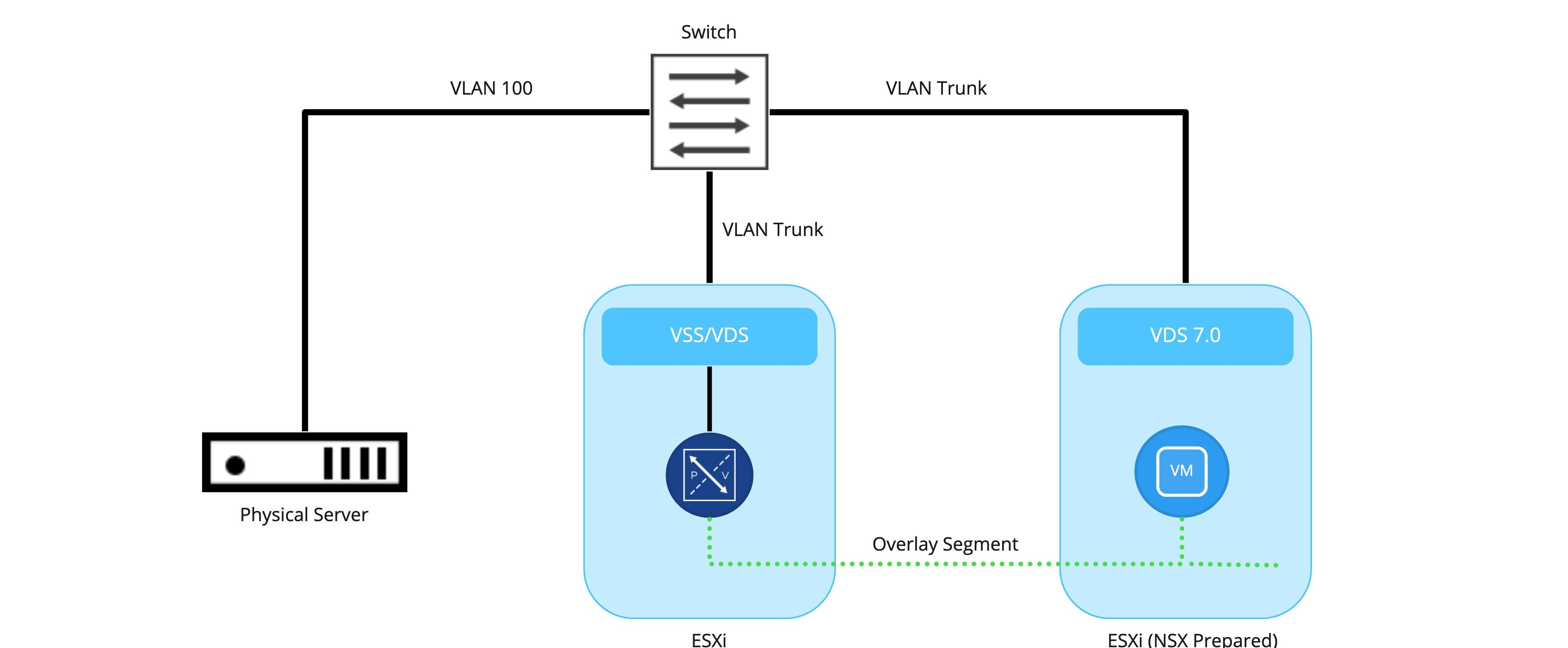
While extremely simplistic (and unlikely given the depiction of only a single physical switch and/or Edge Node VM ), the intent is to depict:
- The physical server is connected to the switch as a VLAN 100 member
- ESXi hosts are also connected to the physical switch and are utilizing VLAN trunks to provide services on different VLANs to VMs or VMKernel (VMK) ports.
- Any communication between the Edge Node VM and the physical server is handled via the physical switch. Here, the traffic for the ESXi host is 802.1q tagged for VLAN 100, while the physical server is just an access port that is configured to be part of VLAN 100.
- Any communication on the overlay side (between the Edge Node VM and the ‘Web’ VM) will be handled by encapsulation of the traffic via the TEP of the Edge Node VM itself (remember, Edge Node VMs have their own TEPs) and the TEP(s) of the ESXi host where the virtual machine resides. In this example, the ESXi host where the Edge Node VM resides does not require NSX-T VIBs.
Edge Node VM and VSS/VDS architecture
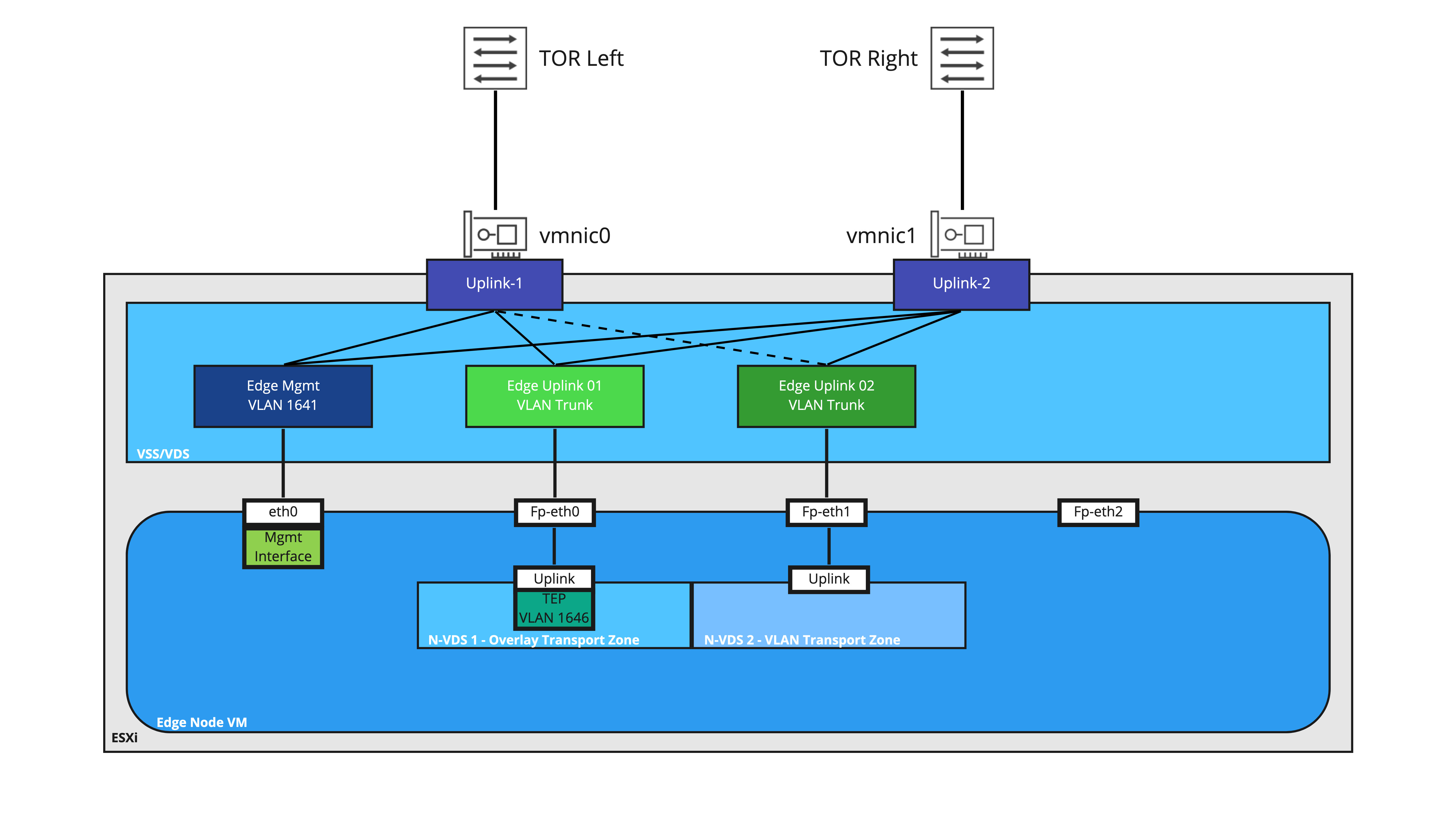
Let’s take a look at the VSS/VDS configuration for an Edge Node VM that has been deployed for bridging purposes. The first interface (‘eth0‘ in the Edge Node OS) is connected a VLAN port group providing access to the management plane of the Edge Node VM (this is the interface where your NSX-T Manager will access the Edge Node VM; it’s also the same interface you would use to access it via SSH, if you’ve elected to allow that in your environment).
In this depiction, the second interface (‘Fp-eth0′ in the Edge Node OS) is where our TEP traffic from the Edge Node VM reaches the VSS/VDS. As mentioned before, when traffic from the Edge Node is destined for a VM utilizing any overlay segment, the traffic is Geneve encapsulated utilizing the Edge Node VM TEP and sent to the appropriate ESXi host TEP where the destination VM resides.
‘Fp-eth0‘ is attached to a VSS/VDS port group configured as a VLAN trunk; this is because the VLAN ID is entered in the Edge profile in NSX-T, resulting in the Geneve encapsulated traffic leaving the Edge Node VM with the proper 802.1q tag.
The third interface (‘Fp-eth1‘ in the Edge Node OS) is providing the VLAN side of the NSX-T bridge and is connected to a VSS/VDS port group configured as a VLAN trunk. This allows the Edge Node VM to bridge multiple segments to VLANs if needed.
As depicted, the fourth interface (‘Fp-eth2‘) is not connected. However, there are many different ways you could configure and utilize an Edge Node VM for bridging where ‘Fp-eth2‘ would be utilized; for example, using an Edge Node VM for both T0 routing and bridging, you’d likely use ‘Fp-eth0‘ and ‘Fp-eth1‘ for both multi-TEP and VLAN route peering traffic, while using ‘Fp-eth2‘ for purely bridging purposes.
While we will be covering this topic in greater detail in the future, the Edge Node VM in the above diagram has two distinct N-VDSes applied to it. ‘N-VDS 1‘ is attached to the Overlay Transport Zone, and as mentioned above, is responsible for any connectivity to NSX Overlay segments via it’s TEP.
‘N-VDS 2‘ has a VLAN Transport Zone attached to it, which means that it will be responsible for any communication from the Edge Node VM on the VLAN side for bridging. When traffic is bridged over from the NSX overlay segment to a target VLAN, this traffic will egress the Edge Node VM via Fp-eth1 as 802.1q tagged traffic.
Ultimately, attaching transport zones to discreet N-VDSes allows us to explicitly dictate which Edge Node VM NIC gets utilized for a given traffic, as well as avoid potential issues that can occur with VLAN ID overlap. We will be devoting a post in the near future to this topic.
Please remember that the above depiction is one of the available methods of configuring an Edge Node VM for bridging; it is certainly not the only way to do so. In coming posts, we will be depicting a different model that you can utilize, which is when you want to utilize your existing Edge Node VM that is providing North/South routing services for bridging as well.
Issues with Edge Node VM bridging and default VSS/VDS settings
Until now, you may think that this works as you believe it should. The Edge Node VM takes frames from the physical server that are destined for the ‘Web’ VM and bridges them to the overlay segment, and vice versa. While that is correct, we must account for the VSS/VDS, and how it learns (or doesn’t learn) MAC addresses. The VSS/VDS also has security features that must be configured to allow bridged traffic.
Referring back to the first diagram, we can see that the Edge Node VM is connected to both a segment and VLAN, and is bridging these two constructs together.
However, as mentioned in the ‘Physical Switch vs Virtual Distributed Switch’ section, a default VSS/VDS only knows about the MAC addresses of the virtual machines that are directly connected to it. This means that while a L2 frame can originate from a VM on a bridged segment and be delivered to a physical server on a VLAN, traffic in the other direction (from the physical server to the VM) will not be delivered to the Edge Node VM.
Why? Because traffic from the physical server to the VM will have an L2 frame destination address of the VM. This means that, while a physical switch can certainly hand this L2 frame to the ESXi server that is hosting the Edge Node VM (this is presuming the physical switch has already observed traffic from the VM to the physical server first), the frame itself would never be handed to the Edge Node VM interface on the VLAN, as the VSS/VDS has absolutely no idea about the MAC address of the VM.
For the diagram below, let’s presume the VM has previously sent an ICMP echo request to the physical server. This frame (containing the ICMP echo request) traversed the Overlay segment to the Edge Node VM, where the Edge Node VM then delivered the frame northbound to the VSS/VDS. In turn, the VSS/VDS delivered it to the physical switch, and then successfully to the physical server.

In Step 1, we see the frame (containing an ICMP echo reply) leaving the physical server, headed for the physical switch. The switch receives the frame, and knows to deliver it to the ESXi server hosting the Edge Node VM. Why? Because of the initial ICMP echo request, the physical switch learned the VM’s MAC address on the port that is attached to the ESXi host.
The switch now sends the frame down the link to the ESXi host, which is depicted in Step 2. So far, so good. However, this is the point where we encounter a problem with the default VSS/VDS settings.
The VSS/VDS natively does not utilize MAC learning; it’s simply programmed with the MAC addresses of the vNICs that utilize it. Once the frame in the above diagram is received, the VSS/VDS finds that the destination MAC address (which is the MAC of the VM) does not match any of the MAC addresses of the virtual machines attached to it (in the above, it would only know the vNIC MACs of the Edge Node VM). As such, the frame is discarded in Step 3.
So how do we ensure bridging will work on the VSS/VDS?
We’ve spent quite a bit of time working on how Edge Node VM bridging works on a VSS/VDS, including the architecture of the vNICs of the Edge Node itself. In Part Three, we’ll review the configuration options necessary to ensure that frames are properly received by the Edge Node VM to allow bridging to operate correctly.
