Creating a Bridge in NSX-T
In previous posts, we reviewed how the Edge Node VM in NSX-T provides bridging, as well as provided a focus on the configurations necessary for bridging to work properly on a VSS/VDS or an NSX-T VLAN segment.
Before moving into the actual steps to create a bridge in NSX-T, let’s tackle an additional topic that you should consider, which is understanding how transport zones can affect your NSX-T bridge configurations.
Please note that the below content is very “segment / logical switch” heavy. For our purposes, these terms (segment and logical switch) are functionally interchangeable.
Transport Zones
In NSX-T, Transport Zones allow administrators to control what networks are made available to hosts and the virtual machines that reside on these hosts. Segments are placed in a given transport zone, and then this transport zone is associated with a host’s N-VDS or vSphere 7.0 VDS. This association allows the host and it’s virtual machines access to the segments that are part of this transport zone.
There are two types of transport zones in NSX-T: overlay transport zones and VLAN transport zones. An overlay transport zone dictates which hosts/VMs can utilize the overlay segments (aka logical switches) in NSX-T. A VLAN transport zone provides hosts/VMs access to all of the VLAN segments that are members.
Typically, an NSX-T deployment requires one of each type of transport zone (although some forego the overlay side of NSX-T and exclusively utilize VLANs.) As such, you will find NSX-T 3.1 preconfigured with two transport zones: ‘nsx-overlay-transportzone‘ and ‘nsx-vlan-transportzone‘.
For more on transport zones and segments, check out the NSX-T Design Guide.
Segment visibility and Transport Zones
Attaching a transport zone to a host (ESXi host, Edge Node VM, etc) makes the segments within it available to the host and/or the virtual machines on that host. It does not mean those segments are actually “on” that host. Once the transport zone is attached; the segments are only realized on a host when they are actually utilized.
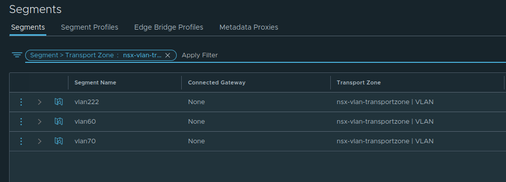
Let’s look at an example. In the below NSX-T environment, we can see there are three VLAN segments named ‘vlan222‘, ‘vlan60‘, and ‘vlan70‘. Each of these VLAN segments is associated with the VLAN ID in their name, so ‘vlan222‘ represents VLAN 222, and so on.
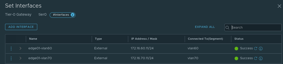
In this same environment we also have an NSX-T Edge Node providing North/South connectivity via a Tier-0 service router (T0 SR). To provide this service, the T0 SR has two uplink interfaces: one on the ‘vlan60‘ segment and one on the ‘vlan70‘ segment. You can see these interfaces and the segment to which they are connected below.
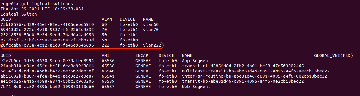
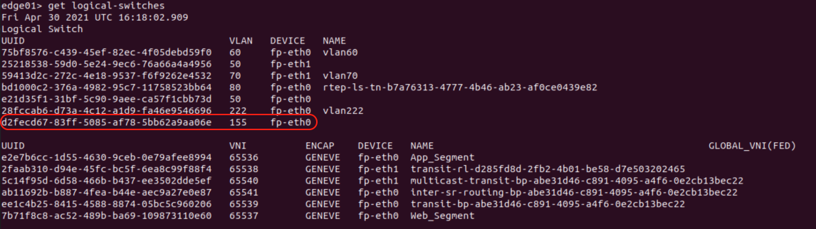
By accessing the CLI of the Edge Node VM, we can display all of the logical switches (Overlay and VLAN) in use on that particular Edge node by utilizing the command ‘get logical-switches’.

The output of ‘get logical-switches‘ provided two lists of logical switches in use on this Edge Node VM: The first is a list of the VLAN logical switches (circled in red), while the second is of all the Overlay logical switches. Keeping our focus on the first list, we can see the logical switch constructs for VLAN 60 and 70 (which are in use by the Tier-0 SR as previously described), and we can see there are two constructs for VLAN 50.
In this environment, VLAN 50 is utilized for the Edge Node VM TEPs, and we are using a multi-TEP architecture; hence you see two “VLAN 50” logical switches, with one associated to the ‘fp-eth0‘ and the other is on ‘fp-eth1‘. We will talk about this a future post regarding Edge Node VM architecture, but we wanted to make sure to touch on what is visible above.
If we contrast this list of VLAN logical-switches against the list of VLAN segments from the NSX-T GUI, you’ll see that the ‘vlan222‘ segment, which represents VLAN 222, does not appear in the list of logical switches on the NSX-T Edge Node. Why? Because the ‘vlan222‘ segment is not utilized by the Edge Node VM in it’s current configuration.
This goes back to our initial point: Attaching a transport zone to a given transport node (ESXi host, Edge Node, etc) does not mean that the segments automatically “exist” on that transport node. What it means is those segments are eligible to be utilized as needed. Once you actually opt to utilize a given segment (by attaching a VM to it, for example), it becomes realized on that transport node.
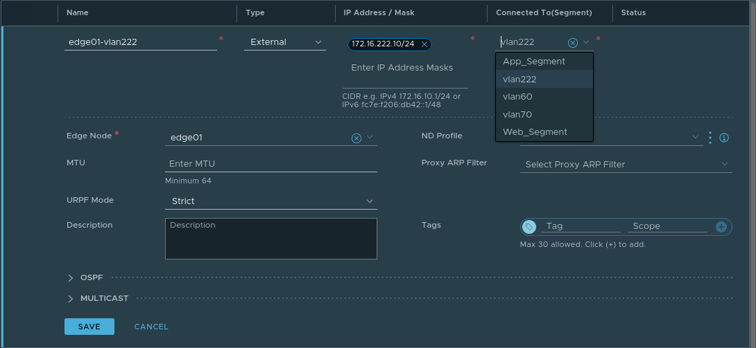
As an example of this, let’s create a new uplink interface on this same Tier-0 SR, utilizing the ‘vlan222‘ segment. Note this Tier-0 SR resides on an Edge Node VM that is attached to both the ‘nsx-overlay-transportzone‘ and ‘nsx-vlan-transportzone‘ transport zones. As such, any segments contained in these transport zones are eligible, and hence, appear in the list of available segments to choose from in the ‘Connected To(Segment) field.
Once the above is saved, let’s now take a look at the output of ‘get logical-switches’ on the Edge Node again.
As the T0 SR on the Edge Node now has an interface on the ‘vlan222‘ segment, we can see that the Edge Node now lists ‘vlan222‘ amongst the other VLAN logical switches.
Potential issues sharing the VLAN Transport Zone
In previous posts, we discussed that an NSX-T Edge VM performing bridging is associating an overlay segment with a VLAN. During the creation of an Edge Bridge, you’ll select an Edge Bridge profile, a Transport Zone, and a VLAN ID (see the below image for an example.) While we will be covering the specific steps in the next post, an “Edge Bridge Profile” is a construct that allows you to select two Edge Nodes that will operate in an Active/Standby configuration for the bridge.
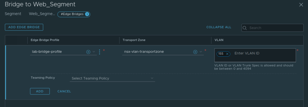
The above demonstrates creating an bridge on the overlay segment named ‘Web_Segment‘. When selecting a transport zone and VLAN ID during the Edge bridge creation, what we are effectively doing is creating a new NSX-T VLAN segment with the associated VLAN ID. You can see the default ‘nsx-vlan-transportzone‘ has been selected, with a VLAN ID of 155 entered for this bridge configuration. This means that a VLAN logical switch with VLAN ID 155 is provisioned only on the Edge Node VMs in the associated Edge Bridge Profile. This is also referred to as creating a ‘local‘ segment on these Edge Node VMs.
You will not find this logical switch listed in your list of Segments ( Networking -> Segments in NSX-T Policy mode) nor will you find it in the list of Logical Switches (Networking -> Logical Switches in NSX-T Manager mode). Below is a look at all of the segments belonging to the ‘nsx-vlan-transportzone’ transport zone after the previously depicted bridge creation.
However, you will find it in the list of logical switches in use on the Edge node itself via the ‘get logical-switches’ command. You will see it below a logical switch utilizing VLAN 155 on device ‘fp-eth0‘.
To recap: creating a bridge results in a VLAN logical switch as a member of a selected transport zone that is only available to the Edge Node VMs that are part of the bridging profile. While this seems innocuous enough, let’s take a look at where and how this could negatively affect you.
VLAN Transport Zones, Edges, and overlapping VLAN IDs
So far, we’ve successfully bridged ‘Web_Segment‘ to VLAN 155 utilizing the same Edge Node VMs that host our Tier-0 SRs for North/South routing. Remember, the Tier-0 SR in our example is connected to VLAN logical switches that reside in the ‘nsx-vlan-transportzone‘ transport zone and our bridge was created using this same transport zone.
Let’s say we have a new need in this same environment: we must bridge another overlay segment (we’ll be using the ‘App_Segment‘ here) to VLAN 70. Recall that the Tier-0 SR residing on these Edge Node VMs is connected to segments that represent VLAN 60 (‘vlan60‘) and 70 (‘vlan70‘) as shown previously in this post.
Following the same steps as above, an Edge Bridge instance is created on ‘App_Segment‘ by selecting the same Edge Bridge Profile, the ‘nsx-vlan-transportzone‘ as our transport zone, and a VLAN ID of 70.
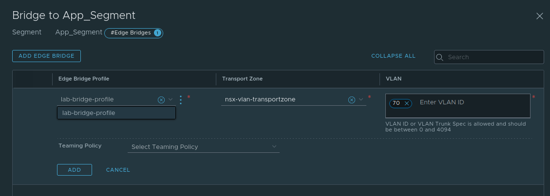
This change is allowed to be Added and Saved, but upon returning to the Segment list, the status of the ‘App_Segment‘ is showing “Failed” with a red bubble. Clicking on “Failed” presents the following error message:

We are being informed the bridge has not been instantiated because the bridge VLAN ID (VLAN 70) is already in use on the underlying host-switch (aka N-VDS). That is, the N-VDS utilized by the Edge Node VM already has a realized logical switch with VLAN id 70, which would be the ‘vlan70‘ VLAN logical switch.
This illustrates an architecture point you must consider: the VLAN id and transport zone for a bridge cannot conflict with another VLAN segment that is already in use on the Edge Node VM as an uplink in that same transport zone. Think of it this way: The Edge Node VM in our above example possesses an N-VDS with VLAN logical switches on VLANs 60 (‘vlan60‘) and 70 (‘vlan70‘) in the ‘nsx-vlan-transportzone‘ transport zone.
When we attempt to create a bridge with a VLAN id of 70 in the ‘nsx-vlan-transportzone‘ transport zone, we’re instructing NSX-T to create a new local VLAN segment that uses VLAN 70. Since the N-VDS already uses VLAN 70 ( via the ‘vlan70‘ segment), this action fails.
How do we work around VLAN ID conflicts like the one above?
There are a few options that you have available to you:
- Avoid bridging to any VLAN that is already utilized on the Edge Node VM.
- Deploy new Edge Node VMs that are explicitly only for bridging
- Deploy a second N-VDS to your existing North/South routing Edge Node VMs
The first options is self-explanatory. If the VLANs that are already in use on the Edge Node VM uplinks are not needed for bridging, then the issue is avoided.
The second option requires deployment of additional Edge Node VMs. As these new Edge Node VMs are not performing any North/South routing, there is no Tier-0 SR on them requiring attachment to VLAN 60 and 70. This would allow the successful creation of a bridge for either VLAN id.
The third option takes a deeper understanding of Edge Node VM architecture. Below is a depiction of an Edge Node VM deployed to an ESXi host. The Edge Node VM has a single N-VDS configured on it, which has been the typical N-VDS deployment model for Edges performing North/South routing since NSX-T 2.5. The ‘fp-eth0‘ and ‘fp–eth1‘ interfaces of the Edge Node VM (which serve as the uplinks for the Edge Node VM N-VDS) are attached to two port groups on the ESXi VDS. Each of these port groups are configured as VLAN trunks.
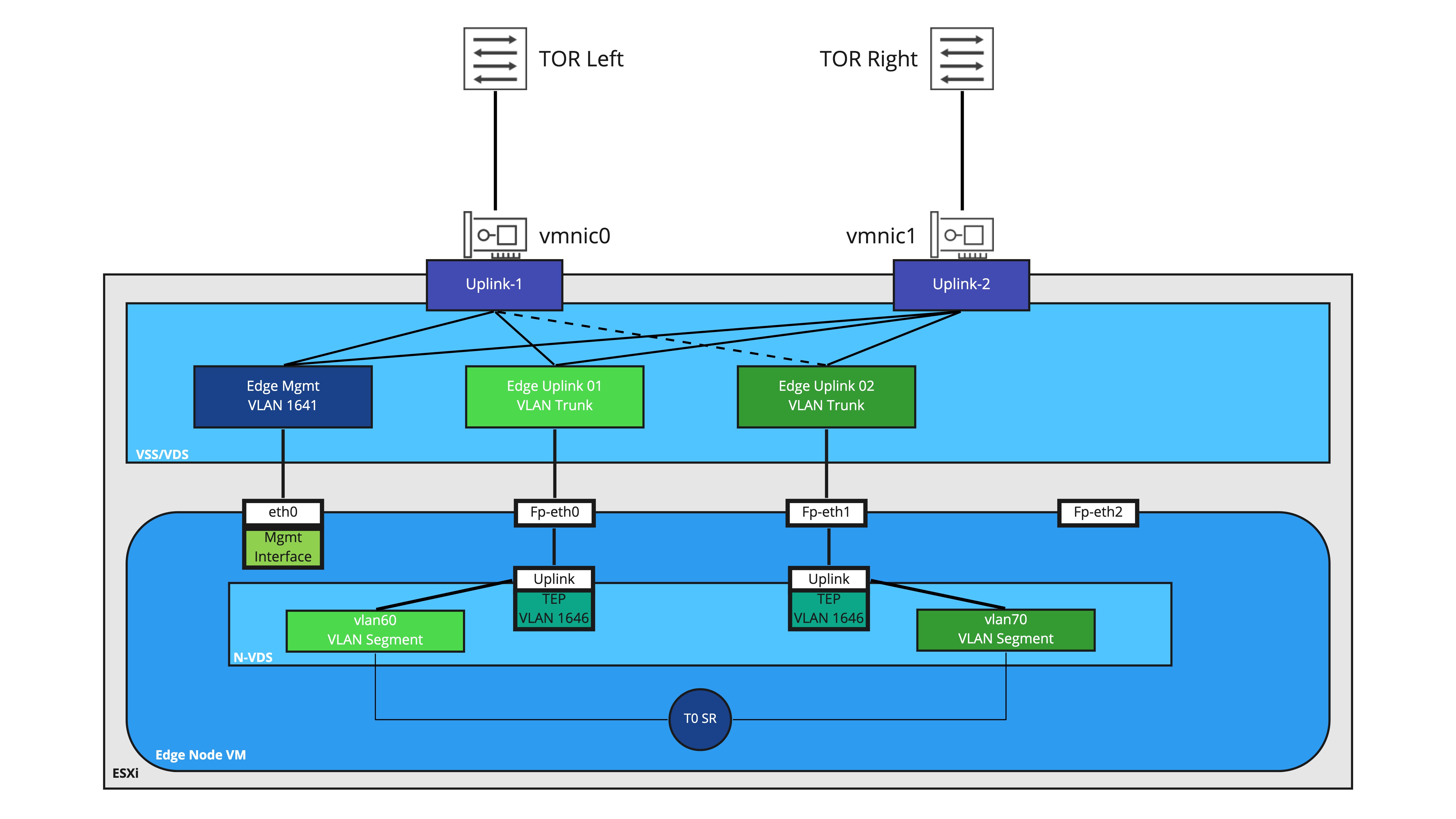
Also depicted is the Tier-0 SR residing on this Edge Node VM, and it’s connections to VLAN segments ‘vlan60‘ and ‘vlan70‘ for North/South routing. Each segment is associated with one of uplinks on the N-VDS for deterministic BGP peering with the physical switching environment.
While reviewing this entire topology in-depth will make a great future topic, the key observation for now is the ‘fp-eth2‘ interface is not utilized. This is normal for an Edge Node VM that is exclusively providing North/South routing services, as there’s really nothing for this interface to do.
However, by creating a new N-VDS and associating it with new VLAN transport zone, we can utilize ‘fp-eth2‘ exclusively for the VLAN side of our bridges. An example of this is below:

Please note in the above diagram, we’ve removed the depiction of the Tier-0 SR and the VLAN segments to make the overall diagram a little easier to consume. In this model, the original transport zones (‘nsx-overlay-transportzone‘ and ‘nsx-vlan-transportzone‘) are associated with ‘N-VDS 1. All overlay connectivity as well as North/South routing is handled on this N-VDS.
‘N-VDS 2‘ has been associated with a new VLAN transport zone (named ‘bridge-transportzone‘) and the sole uplink for this N-VDS is utilizing ‘fp-eth2‘. As depicted here, we’ve even created a new port group on the VDS (‘Edge Uplink 03‘) to provide connectivity to ‘fp-eth2‘. By utilizing a new separate transport zone and N-VDS for bridging, we yield a few benefits:
- A unique VDS port group can be created and utilized for VLAN bridging traffic. This opens up the possibility of determining which pNICs are utilized (as depicted above, ‘Uplink-2‘ is active while ‘Uplink-1‘ is standby for ‘Edge Uplink 03‘.) If you have additional pNICs, you could even utilize discrete connections to keep your bridging VLAN traffic entirely separate from your overlay/routing VLAN traffic.
- You may now bridge to any VLAN you wish, including the VLANs used by the Tier-0 for North/South routing. This is because the logical-switches created for bridging will belong to an entirely separate VLAN transport zone (‘bridge-transportzone‘) versus the ones in use for the Tier-0 SR (which belong to the ‘nsx-vlan-transportzone‘). Even though the VLAN id for these segments are the same, they belong to different transport zones and attached to different N-VDSes. As such, the VLAN id collision we observed in the single N-VDS model is successfully avoided.
Wrap Up
We’ve covered a lot of data here regarding bridging and transport zones. Let’s do a brief recap of everything here:
- A segment/logical switch is a member of a transport zone.
- Creation of a bridge instantiates a local VLAN segment on the Edge Node VMs that are hosting the bridge.
- If using a single VLAN transport zone in an environment, VLAN ids utilized for bridging cannot conflict with VLAN segments utilized by uplinks on an Edge Node VM.
- By utilizing a new VLAN transport zone for bridging, we remove the possibility of VLAN id conflicts as shown above.
In our next post, we will show the step by step of creating a bridge in NSX-T.
