Creating a Bridge in NSX-T
In our previous posts, we’ve covered aspects of bridging in NSX-T utilizing the Edge Node VM, including a focus on the necessary configurations to your vSphere environment. Now let’s look at the actual steps to create a bridge.
Assumptions
Let’s make sure that our environment is ready for the proposed bridging configuration below. Here’s what we should have at this point:
- Two Edge Node VMs deployed to (preferably separate) ESXi hosts.
- The Edge Node VM vNICs should be attached to VSS/VDS port groups or NSX-T segments as depicted in Part Three and Four.
- For this discussion (as there are many ways the Edge Node VM can be connected/configured), we presume that ‘fp-eth0‘ on the Edge Node VM is attached to the N-VDS attached to the overlay transport zone, while ‘fp-eth1‘ is attached to a separate N-VDS with a VLAN transport Zone created for bridging. (see Part Four for N-VDS and Transport Zones discussions.) See below for an example of this configuration:

In NSX-T 3.1, there are three steps to create a bridge:
- Create an Edge cluster or select an existing one
- Create an Edge Bridge profile
- Add an Edge Bridge to a segment
1. Create an Edge Cluster or select an existing one
To utilize a bridge, we first must create an Edge cluster that will host our bridge or select an existing Edge cluster. An Edge cluster is a logical construct that groups our Edge nodes (be they bare metal Edge nodes or VM Edge nodes) together. This allows Edges to be utilized with a common purpose, such as bridging.
If deploying new Edge Node VMs for the purposes of bridging, we recommend creating a new Edge cluster. This will make things clearer insofar as identifying an Edge Cluster which is performing North/South routing vs one that has been created to solely support bridging.
On that same note, if your intent is to re-utilize existing Edge Node VMs for bridging; for instance, configuring the unused ‘fp-eth2‘ interface of the Edge Node VM as depicted in Part Four, then there’s no need to create a new Edge Cluster. You’ll simply select to use your existing Edge Cluster in step 2 below.
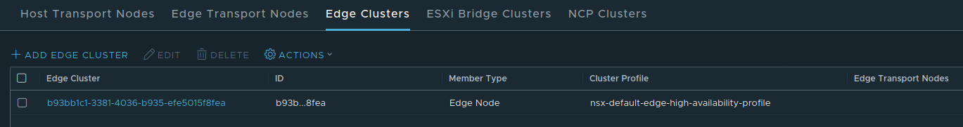
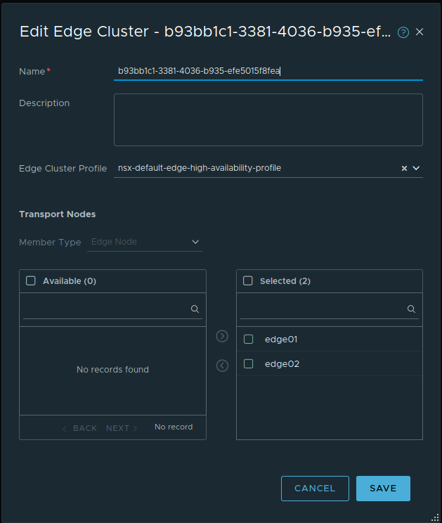
An Edge Cluster is created under System -> Fabric -> Nodes and then going to Edge Clusters. Creating a Edge cluster is as simple as clicking ‘Add Edge Cluster’, providing a name, selecting the Edge Cluster profile, and then selecting the Edge nodes you wish to be part of the cluster.
2. Create an Edge Bridge Profile
Creating an Edge Bridge profile is performed under Networking -> Segments -> Edge Bridge Profiles. When creating a bridge profile, you will select:
- The target edge cluster that will provide bridging services
- Choose the Primary Edge Node.
- Choose the Secondary Edge Node.
- Choose between Preemptive and Non Preemptive fail over

A given bridge instance in NSX-T is hosted on two Edge nodes; one Edge node will be the active participant (Primary Node) in the bridge, and the other edge node will be standing by to take over in case the active Edge node goes down (Backup Node). (When creating an Edge Bridge profile, you may observe there is an ‘HA Mode‘ field that is set to ‘Active Standby‘; as of NSX-T 3.1, this field cannot be altered.)
You will choose your Primary and Backup Nodes from the membership of the selected Edge Cluster. For example, if you have deployed two Edge Nodes that you wish to exclusively use for bridging, you must first place them in an Edge Cluster (this could be a new Edge Cluster or an existing one) and then select that Edge Cluster in the Edge Bridge profile.
Lastly, you will choose between Preemptive and Non Preemptive Fail Over. To evaluate the difference between these Fail Over settings, envision Edge Node 01 (EN01) is set to ‘Primary‘, with Edge Node 02 (EN02) as ‘Backup‘. With this configuration, EN01 is the Active participant in the bridge during normal operations. If EN01 goes down, EN02 will become the Active participant and will continue providing bridging services for any segments using this Edge Bridge profile.
With Preemptive Fail Over, when EN01 comes back online, it will resume being the Active instance for the bridge, and EN02 will return to Standby. Conversely, if the Edge Bridge profile is configured for Non Preemptive, EN02 will continue being the Active instance even when EN01 returns to service.
3. Add an Edge Bridge to a segment
Now that we have our Edge cluster and the Edge Bridge profile, we can create an Edge Bridge instance on our desired segment. Keep in mind that the NSX Edge Bridge is designed to bridge an overlay segment with a VLAN; while you will see the your overlay transport zone in drop down list under ‘Transport Zone‘, you will receive an error message if you attempt to select it and then save the configuration.
To begin, choose to edit the target overlay segment, and then click ‘Set‘ in the Edge Bridges section:

Now click the ‘Add Edge Bridge‘ button at the top left, and you’ll be prompted to add the data to create the Edge Bridge. Specifically, you’ll need 3 pieces of data:
- The Edge Bridge profile that you wish to use (in the example below, the profile is named ‘lab-bridge‘)
- The target VLAN Transport Zone that you wish to utilize (below we’ve chosen the ‘bridge-transportzone‘)
- The VLAN ID to which you wish to bridge this particular overlay segment (VLAN ID 155 is entered below)

You may also choose a Teaming policy. This setting can be useful if the underlying Edge N-VDS attached to your bridging VLAN transport zone has multiple uplinks; a teaming policy allows you to ensure that traffic utilizes a selected uplink. This is not a mandatory setting to configure; if you have multiple uplinks and no teaming policies, a single uplink is selected from your N-VDS for bridging by NSX-T.
At this point, once you hit ‘Add’, and then ‘Apply’ at the bottom, you’ll be returned to the main Segment screen itself, where you will then choose ‘Save’. At this point, you’ve successfully created a NSX-T overlay to VLAN bridge!
Understanding Edge Bridge Profiles
Previously, we discussed the configuration options available for Edge Bridge profiles. What we’d like to do now is take a moment to explore the flexibility that Edge Bridge profiles provide. What may not be readily apparent is that an Edge Node can be ‘Primary Node‘ in one Edge Bridge profile, while being ‘Backup Node‘ in another. Below is a depiction of two Edge Node VMs that provide bridging services in an environment and how we can configure Edge Bridge profiles between them.

You can see that we have two Edge Bridging profiles: ‘bridge-profile-1‘ and ‘bridge-profile-2‘. ‘Bridge-profile-1‘ has Edge Node 01 (EN01) as Primary with Edge Node 02 as Backup, while ‘bridge-profile-2′ has just the opposite; EN02 is Primary and EN01 is Backup.
For each bridging instance, you may select the Edge Bridge profile that you wish to use. In the above depicted environment, rather than loading all of the “active” bridge instances on EN01 while EN02 sits idly, you may instead split the “active” bridge instances between the two Edge Nodes.
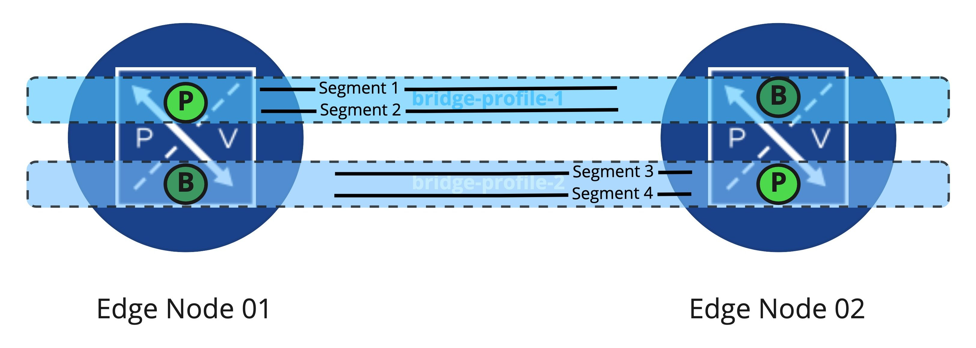
As depicted above, we’ve taken 4 segments being bridged to VLANs, and have configured an “Active/Active” model between the Edge Nodes. Segments 1 and 2 have the ‘Primary‘ bridge instances on EN01, while segments 3 and 4 find their ‘Primary‘ bridge instances on EN02. Using this configuration, both Edge Node VMs are actively working as bridges, just on different segments.
In the event of a EN01’s failure, the bridging instances for segments 1 and 2 are moved over to EN02, as EN02 was the ‘Backup Node‘ for the associated Edge Bridge profile. The bridging instances for segments 3 and 4 are unaffected by EN01’s failure; they continue utilizing EN02. If ‘bridge-profile-1‘ is configured for ‘Preemptive‘, the bridging instances for segments 1 and 2 return to EN01 after it returns to service.
While the idea of multiple Edge Bridge profiles is simplistic with only two Edge Nodes from which to choose, doubling from two Edge Nodes to four dramatically increases the potential number of Edge Bridge profiles you could create.

As you may configure two Edge Bridge profiles for each pair of Edge Nodes, if every possible Edge Bridge profile was created between the above Edge Nodes, you’d have 12 distinct Edge Bridge profiles (identified as BP in the diagram) from which to choose. Obviously, adding more Edge Nodes brings the potential combinations even higher; you can evaluate the number of available pairings by solving N(N-1) where “N” is the count of Edge Nodes.
All this being said, it’s unlikely you would require all of these Edge Bridge profile permutations in your environment; the above was depicted to reinforce that any Edge performing bridging can be a ‘Primary Node‘ in some Edge Bridge profiles while also being a ‘Backup Node‘ in others. How you opt to utilize Edge Bridge profiles (and ultimately bridging itself) is fully up to you.
Next time….
Hopefully you’ve found this entire series useful to fully understanding how bridging in NSX-T works in conjunction with Edge Node VMs. In our next post on the topic, we plan to really get into what is happening “under the hood”, so to speak, when you create a bridging instance. See you then!
